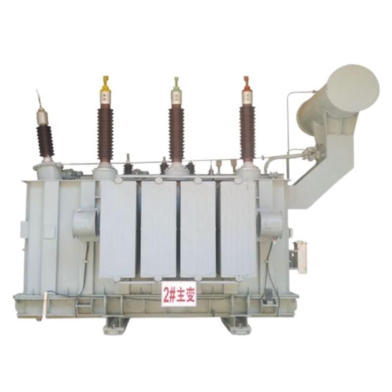
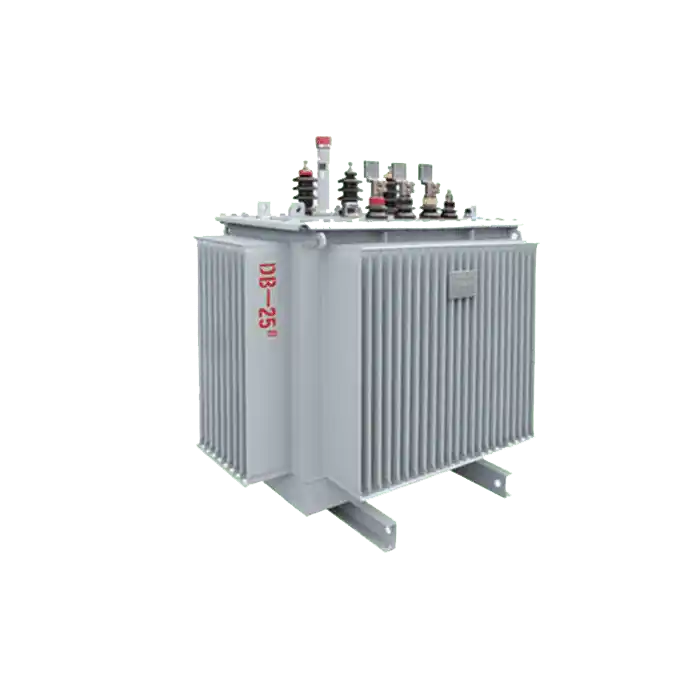
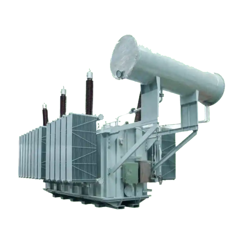
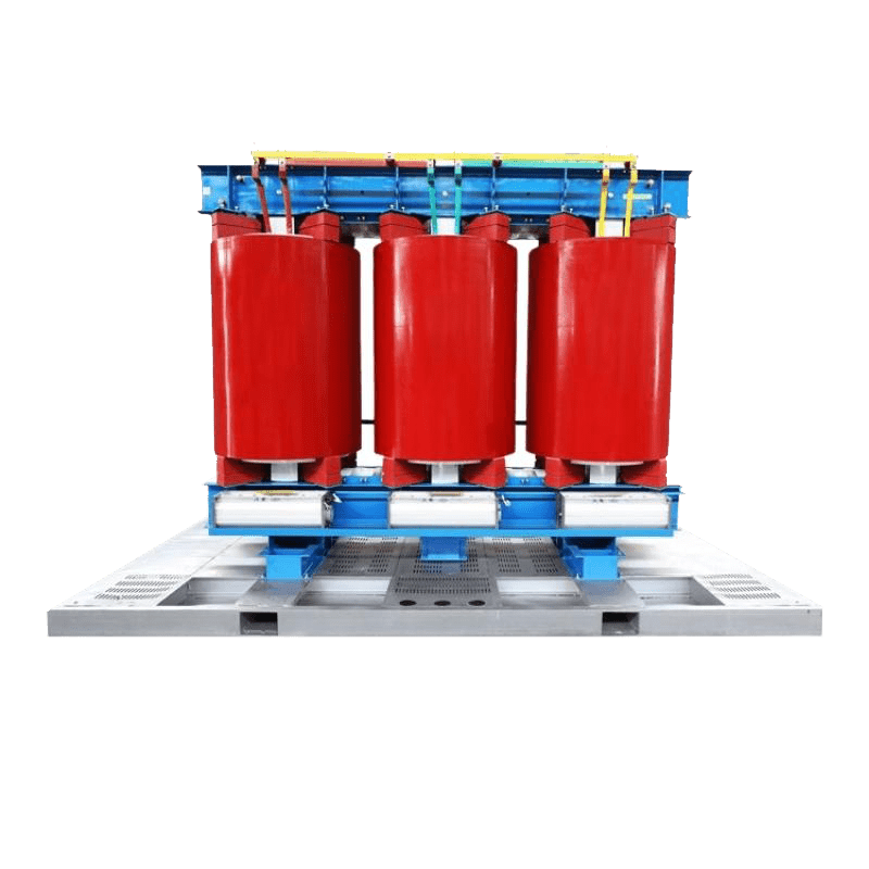
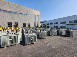
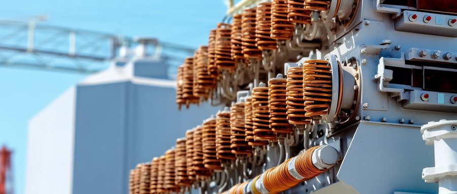
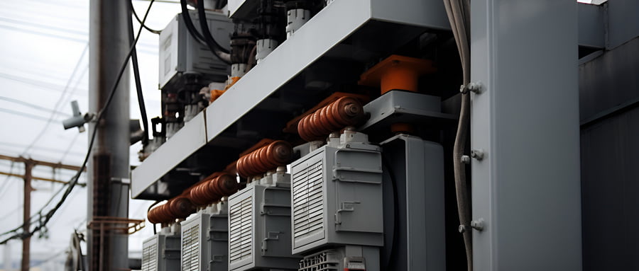
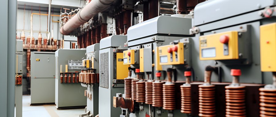
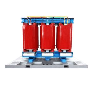
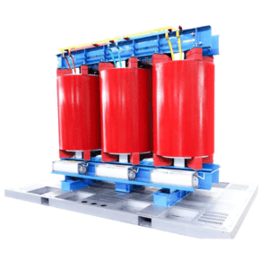
33kv cast resin dry type distribution transformer
Primary Voltage Rating:33KV,34.5KV,35KV,38.5KV
Secondary Voltage:0.4kv or others
Rated power:30kva-16000kva
H.V. TAP RANGE: ±2×2.5%
Winding connection: Dyn11/ Yyn0
Winding material: Copper/Aluminum
Cooling Method: AN / AF
Tapping Method: OLTC/OCTC
Standard:IEC60076,GB20052-2020,ISO9001,ANSI,CSA
Min. order quantity: ≧ 1 set
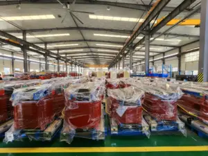
Packaging Details: International wooden cases or according to the actual transport needs
delivery time: Generally it is 20 days if the goods are in stock, or 30 days if the goods are not. It is according to the quantity.
Payment Method: TT, Western Union, L/C
GE Transformer introduces advanced European technology and optimizes the design of epoxy resin cast dry-type transformers through patented technology and special software. The core of this product is made of high-quality oriented cold-rolled silicon steel sheet material and adopts a new step-joint technology to improve the no-load performance of the core greatly. The coil uses American Huntsman epoxy resin. This product has good resin permeability and no bubbles, so the amount of partial discharge is small. The high and low voltage coils are closely matched and have strong structural strength, thus ensuring strong short circuit resistance and vibration resistance. This product has a service life of 30 years under normal use conditions. During the operating life period, the product will not cause cracks on the coil surface due to temperature changes under normal use conditions.
Advantages of 33KV dry-type transformers:
GE Transformer introduces advanced European technology and optimizes the design of epoxy resin cast dry-type transformers through patented technology and special software. The core of this product is made of high-quality oriented cold-rolled silicon steel sheet material and adopts a new step-joint technology to improve the no-load performance of the core greatly. The coil uses American Huntsman epoxy resin. This product has good resin permeability and no bubbles, so the amount of partial discharge is small. The high and low-voltage coils are closely matched and have strong structural strength, thus ensuring strong short-circuit resistance and vibration resistance. This product has a service life of 30 years under normal use conditions. During the operating life period, the product will not cause cracks on the coil surface due to temperature changes under normal use conditions.
Low noise and low loss
- The noise source of the transformer comes from the iron core. Our company uses the first imported German
GEORG’s step-jointed core automatic production line adopts the new Step-Lap process to improve the magnetic circuit distribution inside the core and reduce the noise of the product with its unique equipment advantages. - The product uses high-quality silicon steel sheets and a lower magnetic density to keep it away from the saturation point, so that the amount of harmonics in the core is reduced, reducing noise and no-load losses.
- All clamping parts are buffered with silicone rubber and elastic elements to reduce amplitude and noise. At the same time, the outer surface of the core is cured to provide sound insulation.
Flame retardant and does not pollute the environment
- Solid insulation composed of high-quality resin has high electrical strength (breakdown voltage is not less than 34kV/mm), small partial discharge, and can be controlled within the range of ≤5pC.
- Since the resin material used in dry-type transformers generates very little heat when burned (approximately
65mJ/kg), so it has the characteristics of flame retardant and self-extinguishing, and will not produce an arc due to a short circuit. The resin will not produce toxic and harmful gases under high heat. - The coil does not absorb moisture, and the surface of the core is cured, so it can be used in the relative humidity of the air.
It operates reliably in 100% of environments and does not require dehumidification treatment for intermittent operation. - Dry-type transformers also have strong overload capacity, good thermal stability, small size,
It has the advantages of being lightweight, simple convenient to install, and maintenance-free. Widely used in high-rise buildings, commercial centers, airports, stations, docks, subways, factories and underground distribution stations, etc.
Forced Cooling
The cooling methods of dry-type transformers are divided into natural air cooling (AN) and forced air cooling (AF). When naturally air cooled (AN), under normal use conditions, the transformer can continuously output 100% of the rated capacity. When forced air cooling (AF) is used, the short-term output capacity of the transformer can be increased by 30% under normal use conditions, and is suitable for various emergency overload or intermittent overload operations
Temperature Control System
The temperature control system consists of a temperature controller and a Pt100 platinum resistance temperature sensor installed at the hottest point of the product. The temperature controller has the function of temperature display and control. It can continuously display and control the temperature of each phase of the transformer. If the temperature of the transformer winding is too high due to overload operation or failure, the temperature controller can send out an alarm signal; when the winding temperature exceeds the safe value can send out a trip signal. When forced air cooling is used, the temperature controller automatically starts and stops the fan according to the winding temperature. It can provide temperature monitoring of transformer windings and iron cores, 4~20mA analog output or RS485 computer interface according to user needs, adapting to the needs of modern power operation automation management
Using Environment
Altitude: Conventional is used below 2000 meters, more than 2000 meters need to be customized
Ambient temperature:
Highest air temperature +45ºC
Minimum outdoor air temperature -15ºC
Scope of application:
33KV dry type transformer can be used for power distribution in heavy load centers represented by commercial areas, factories, hospitals, airports, tunnels, chemical factories, shipyards, etc.
| Technical Parameters for 35kV Cast Resin Dry-type Distribution Transformer | |||||||
| Capacity (kVA) | Model | HV Voltage (KV) | LV Voltage (KV) | No load loss (kW) | Load loss (kW) 120℃ | No load current (%) | Short- circuit impedance (%) |
| 50 | SC10-50/35 SC11-50/35 SC12-50/35 SC13-50/35 | 35 38.5 | 0.4 | 0.450 0.405 0.360 0.360 | 1.42 1.42 1.42 1.28 | 2.3 2.3 2.3 2.3 | 6.0 6.0 6.0 6.0 |
| 100 | SC10-100/35 SC11-100/35 SC12-100/35 SC13-100/35 | 0.630 0.567 0.504 0.504 | 2.09 2.09 2.09 1.88 | 2.0 2.0 2.0 2.0 | 6.0 6.0 6.0 6.0 | ||
| 160 | SC10-160/35 SC11-160/35 SC12-160/35 SC13-160/35 | 0.790 0.710 0.630 0.630 | 2.81 2.81 2.81 2.53 | 1.5 1.5 1.5 1.5 | 6.0 6.0 6.0 6.0 | ||
| 200 | SC10-200/35 SC11-200/35 SC12-200/35 SC13-200/35 | 0.880 0.790 0.705 0.705 | 3.32 3.32 3.32 2.90 | 1.5 1.5 1.5 1.5 | 6.0 6.0 6.0 6.0 | ||
| 250 | SC10-250/35 SC11-250/35 SC12-250/35 SC13-250/35 | 0.990 0.890 0.790 0.790 | 3.80 3.80 3.80 3.42 | 1.3 1.3 1.3 1.3 | 6.0 6.0 6.0 6.0 | ||
| 315 | SCB10-315/35 SCB11-315/35 SCB12-315/35 SCB13-315/35 | 1.17 1.05 0.940 0.940 | 4.51 4.51 4.51 4.06 | 1.3 1.3 1.3 1.3 | 6.0 6.0 6.0 6.0 | ||
| 400 | SCB10-400/35 SCB11-400/35 SCB12-400/35 SCB13-400/35 | 1.37 1.23 1.10 1.10 | 5.41 5.41 5.41 4.87 | 1.1 1.1 1.1 1.1 | 6.0 6.0 6.0 6.0 | ||
| 500 | SCB10-500/35 SCB11-500/35 SCB12-500/35 SCB13-500/35 | 1.62 1.46 1.30 1.30 | 6.65 6.65 6.65 5.99 | 1.1 1.1 1.1 1.1 | 6.0 6.0 6.0 6.0 | ||
| 630 | SCB10-630/35 SCB11-630/35 SCB12-630/35 SCB13-630/35 | 1.86 1.67 1.49 1.49 | 7.69 7.69 7.69 6.92 | 1.0 1.0 1.0 1.0 | 6.0 6.0 6.0 6.0 | ||
| 800 | SCB10-800/35 SCB11-800/35 SCB12-800/35 SCB13-800/35 | 2.16 1.95 1.73 1.73 | 9.12 9.12 9.12 8.20 | 1.0 1.0 1.0 1.0 | 6.0 6.0 6.0 6.0 | ||
| 1000 | SCB10-1000/35 SCB11-1000/35 SCB12-1000/35 SCB13-1000/35 | 2.43 2.19 1.95 1.95 | 10.4 10.4 10.4 9.36 | 0.75 0.75 0.75 0.75 | 6.0 6.0 6.0 6.0 | ||
| 1250 | SCB10-1250/35 SCB11-1250/35 SCB12-1250/35 SCB13-1250/35 | 2.83 2.55 2.26 2.26 | 12.7 12.7 12.7 11.4 | 0.75 0.75 0.75 0.75 | 6.0 6.0 6.0 6.0 | ||
| 1600 | SCB10-1600/35 SCB11-1600/35 SCB12-1600/35 SCB13-1600/35 | 3.24 2.92 2.60 2.60 | 15.4 15.4 15.4 13.9 | 0.75 0.75 0.75 0.75 | 6.0 6.0 6.0 6.0 | ||
| 2000 | SCB10-2000/35 SCB11-2000/35 SCB12-2000/35 SCB13-2000/35 | 3.82 3.44 3.06 3.06 | 18.2 18.2 18.2 16.4 | 0.75 0.75 0.75 0.75 | 6.0 6.0 6.0 6.0 | ||
| 2500 | SCB10-2500/35 SCB11-2500/35 SCB12-2500/35 SCB13-2500/35 | 4.45 4.01 3.56 3.56 | 21.8 21.8 21.8 19.6 | 0.75 0.75 0.75 0.75 | 6.0 6.0 6.0 6.0 | ||
| Technical Parameters for 35KV Dry-type Power Transformer | |||||||
Capacity (KVA) | Model | HV Voltage (KV) | LV Voltage (KV) | No load loss kW) | Load loss kW) 120℃ | No load current (%) | Short- circuit mpedance (%) |
| 800 | SC10-800/35 SC11-800/35 SC12-800/35 SC13-800/35 | 35 38.5 | 6 10 | 2.25 2.02 1.80 1.80 | 9.40 9.40 9.40 8.50 | 0.95 0.95 0.95 0.95 | 60 6.0 6.0 60 |
| 1000 | SC10-1000/35 SC11-1000/35 SC12-1000/35 SC13-1000/35 | 2.67 2.40 2.14 2.14 | 10.9 10.9 10.9 9.80 | 0.95 0.95 0.95 0.95 | 6.0 6.0 6.0 6.0 | ||
| 1250 | SC10-1250/35 SC11-1250/35 SC12-1250/35 SC13-1250/35 | 3.13 2.82 2.50 2.50 | 12.9 12.9 12.9 11.6 | 0.85 0.85 0.85 0.85 | 6.0 6.0 6.0 6.0 | ||
| 1600 | SC10-1600/35 SC11-1600/35 SC12-1600/35 SC13-1600/35 | 3.69 3.32 2.95 2.95 | 15.4 15.4 15.4 13.9 | 0.85 0.85 0.85 0.85 | 6.0 6.0 6.0 6.0 | ||
| 2000 | SC10-2000/35 SC11-2000/35 SC12-2000/35 SC13-2000/35 | 4.23 3.81 3.38 3.38 | 18.2 18.2 18.2 16.4 | 0.75 0.75 0.75 0.75 | 7.0 7.0 70 7.0 | ||
| 2500 | SC10-2500/35 SC11-2500/35 SC12-2500/35 SC13-2500/35 | 4.86 4.37 3.89 3.89 | 21.8 21.8 21.8 19.7 | 0.75 0.75 0.75 0.75 | 7.0 7.0 7.0 7.0 | ||
| 3150 | SC10-3150/35 SC11-3150/35 SC12-3150/35 SC13-3150/35 | 6.03 5.43 4.82 4.82 | 24.5 24.5 24.5 22.1 | 0.70 0.70 0.70 0.70 | 8.0 8.0 8.0 8.0 | ||
| 4000 | SC10-4000/35 SC11-4000/35 SC12-4000/35 SC13-4000/35 | 7.02 6.31 5.61 5.61 | 29.4 29.4 29.4 26.5 | 0.70 0.70 0.70 0.70 | 8.0 8.0 8.0 8.0 | ||
| 5000 | SC10-5000/35 SC11-5000/35 SC12-5000/35 SC13-5000/35 | 8.37 7.53 6.96 6.96 | 34.9 34.9 34.9 31.4 | 0.60 0.60 0.60 0.60 | 8.0 8.0 8.0 8.0 | ||
| 6300 | SC10-6300/35 SC11-6300/35 SC12-6300/35 SC13-6300/35 | 9.90 8.91 7.92 7.92 | 40.8 40.8 40.8 36.7 | 0.60 0.60 0.60 0.60 | 8.0 8.0 8.0 8.0 | ||
| 8000 | SC10-8000/35 SC11-8000/35 SC12-8000/35 SC13-8000/35 | 35 38.5 | 6 10 | 11.3 10.2 9.04 9.04 | 46.0 46.0 46.0 41.4 | 0.50 0.50 0.50 0.50 | 9.0 9.0 9.0 9.0 |
| 10000 | SC10-10000/35 SC11-10000/35 SC12-10000/35 SC13-10000/35 | 12.9 11.6 10.3 10.3 | 55.5 55.5 55.5 49.9 | 0.50 0.50 0.50 0.50 | 9.0 9.0 9.0 9.0 | ||
| 12500 | SC10-12500/35 SC11-12500/35 SC12-12500/35 SC13-12500/35 | 15.7 14.1 12.6 12.6 | 64.6 64.6 64.6 58.2 | 0.40 0.40 0.40 0.40 | 9.0 9.0 9.0 9.0 | ||
| 16000 | SC10-16000/35 SC11-16000/35 SC12-16000/35 SC13-16000/35 | 19.3 17.4 15.5 15.5 | 76.0 76.0 76.0 68.4 | 0.40 0.40 0.40 0.40 | 9.0 9.0 9.0 9.0 | ||
