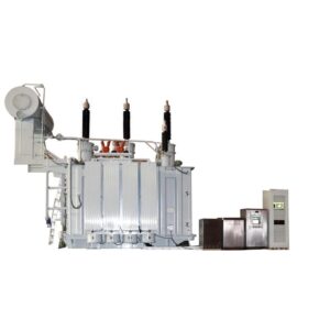
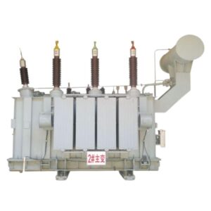
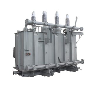
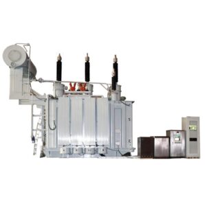
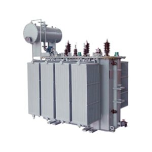
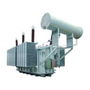
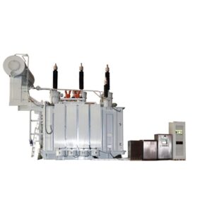
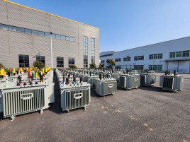
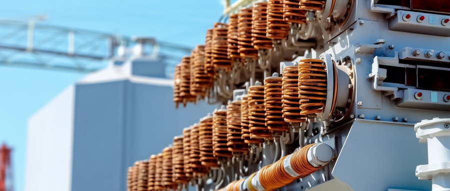
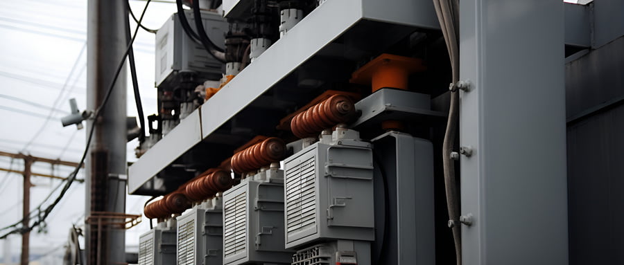
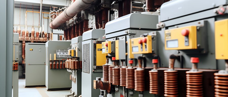
35KV class three phase oil immersed distribution transformer
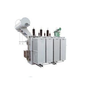
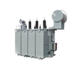
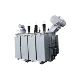
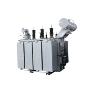
Primary Voltage Rating: 33KV,34.5KV,35KV,38.5KV,40.5KV,44KV or other
Secondary Voltage: 0.4KV
Rated power: 630-31500kva
H.V. TAP RANGE: ±2×2.5%
Winding connection: Dyn11/ Yyn0
Winding material: Copper/Aluminum
Cooling Method: ONAN / ONAF
Tapping Method: NLTC/OCTC
Standard:IEC60076,ISO9001,GB,ANSI,CSA
Min. order quantity: ≧ 1 set
Packaging Details: International wooden cases or according to the actual transport needs
delivery time: Generally it is 20 days if the goods are in stock, or 30 days if the goods are not. It is according to the quantity.
Payment Method: TT, Western Union, L/C
GE Ttransformer’s 35KV series of power transformers are more advanced in design, with significant improvements and enhancements in materials, construction, and workmanship. The high-voltage and low-voltage clamping elements are tensioned with steel straps or upper and side beams to form a strong frame structure, which enhances the clamping strength of the iron core and its resistance to transport shocks. It has strong short-circuit resistance, a beautiful appearance, reliable operation, low loss, and low noise, and has reached the advanced level of similar products overseas. Our SZ13-20000/35 transformer has passed the sudden short-circuit test conducted by the National Transformer Testing Centre. The longitudinal oil channel in the high-voltage coil is conducive to heat dissipation and can significantly reduce the temperature difference between the copper foil and the hottest spot inside the coil.
35KV oil-immersed transformer feature:
1. The iron core is made of high-quality, low-consumption high-permeability cold-rolled grain-oriented silicon steel sheet, five-level fully oblique seam vertical piece form, combined with the shearing and stacking process mentioned above, the entire iron core is fastened reliably and balanced in force, no-load loss, air flow, and noise are all better than national standards.
2. The high-voltage and low-voltage windings are made of high-quality copper wires or copper foils. There is no helix angle at the end of the foil windings, which reduces the transverse magnetic flux leakage caused by ampere-turn imbalance, improves the axial stability of the transformer, and ensures interlayer insulation. High-density, high-electric-strength epoxy-adhesive insulating paper is used to form a solid whole after curing, with good short-circuit resistance and impact resistance.
3. Use simulation software to simulate the distribution of the winding mixing field, reasonably arrange the heat exploration channels inside and outside the winding, reduce the temperature difference between layers, reduce the temperature of hot spots, slow down the aging speed of the edge in the thermal state, and prolong the service life of the transformer
4. The traditional lead wire welding method is canceled, and the high and low voltage lead wires are connected by cold crimping and bolts, and the cleanliness of the body is higher.
5. The high and low voltage bushings adopt the internal fixed structure of the oil tank, the upper part of the tank cover has no corrosion problem of the compression parts, the outer surface of the oil tank is statically sprayed, the coating adhesion rod, the anti-corrosion parts are good, and the transformer has a simple appearance and a generous appearance.
Conditions of Use:
Altitude: ≤2000m, high altitude can be customized separately
Maximum ambient temperature: + 40°C
Maximum annual average temperature: +20°C
Maximum daily average temperature: +30°C
Minimum outdoor temperature: -45°C
| Type | Rated power (KVA) | Connection type | Vollage combination(KV) | Load Loss(W) | No-load current(%} | Short-circuit impedance(%) | |||
| High voltage | Tapping range | Low voltage | Dy Yy | ||||||
| S11-630 | 630 | Yd11 | 35 | ±5% | 3.15 6.3 10.5 | 830 | 7870 | 1.10 | 6.5 |
| S11-800 | 800 | 980 | 9410 | 1.00 | |||||
| S11-1000 | 1000 | 1150 | 11540 | 1.00 | |||||
| S11-1250 | 1250 | 1410 | 13940 | 0.90 | |||||
| S11-1600 | 1600 | 1700 | 16670 | 0.80 | |||||
| S11-2000 | 2000 | 2180 | 18380 | 0.70 | |||||
| S11-2500 | 2500 | 2560 | 19670 | 0.60 | |||||
| S11-3150 | 3150 | 35~38.5 | ±5% | 3.15 6.3 10.5 | 3040 | 23090 | 0.56 | 7.0 | |
| S11-4000 | 4000 | 3620 | 27360 | 0.56 | |||||
| S11-5000 | 5000 | 4320 | 31380 | 0.48 | |||||
| S11-6300 | 6300 | 5250 | 35060 | 0.48 | 7.5 | ||||
| S11-8000 | 8000 | YNd11 | 35~38.5 | ±5% or ±2×2.5% | 3.15 3.3 6.3 6.6 10.5 11 | 7200 | 38500 | 0.42 | |
| S11-10000 | 10000 | 8700 | 45300 | 0.42 | |||||
| S11-12500 | 12500 | 10080 | 53900 | 0.40 | 8.0 | ||||
| S11-16000 | 16000 | 12160 | 65800 | 0.40 | |||||
| S11-20000 | 20000 | 14400 | 79500 | 0.40 | |||||
| S11-25000 | 25000 | 17020 | 94100 | 0.32 | |||||
| S11-31500 | 31500 | 20220 | 112900 | 0.32 | |||||
| Type | Rated power (KVA) | Connection type | voltage combination(KV) | No-load loss | Load Loss(W) | No-load current(%) | Shorl-circuit impedance(%) | ||
| High voltage | Tanging rang | Low voltage | |||||||
| SZ11-2000 | 2000 | Yd11 | 35 | ±3×2.5% | 6.3 10.5 | 2300 | 19240 | 0.80 | 6.5 |
| SZ11-2500 | 2500 | 2720 | 20640 | 0.80 | |||||
| SZ11-3150 | 3150 | 35~38.5 | ±3×2.5% | 6.3 10.5 | 3230 | 24710 | 0.72 | 7.0 | |
| SZ11-4000 | 4000 | 3870 | 29160 | 0.72 | |||||
| SZ11-5000 | 5000 | 4640 | 34200 | 0.68 | |||||
| SZ11-6300 | 6300 | 5630 | 36800 | 0.68 | 7.5 | ||||
| SZ11-8000 | 8000 | YNd11 | 35~38.5 | ±3×2.5% | 6.3 6.6 10.5 11 | 7870 | 40600 | 0.60 | |
| SZ11-10000 | 10000 | 9280 | 48100 | 0.60 | |||||
| SZ11-12500 | 12500 | 10940 | 56900 | 0.56 | 8.0 | ||||
| SZ11-16000 | 16000 | 13170 | 70300 | 0.54 | |||||
| SZ11-20000 | 20000 | 15570 | 82800 | 0.54 | |||||
