Transformers and inductors are coils wound around magnetic cores, and they seem to be called inductors. So how do we understand transformers and inductors? Or we should first understand the hidden inductance of transformers – excitation or excitation inductance, and then analyze the role and use of transformers. In short, we should re-understand transformers to eliminate our confusion.
Before we delve into transformers, we need to understand some basic electromagnetic principles. Electromagnetism is the science of studying the interaction between charge, current, and magnetic field. Among them, Faraday’s law of electromagnetic induction is the key to understanding the working principle of transformers.
Faraday’s law of electromagnetic induction states that when the magnetic flux in a conductor loop changes, an induced electromotive force will be generated in the conductor.
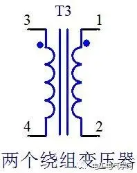
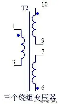
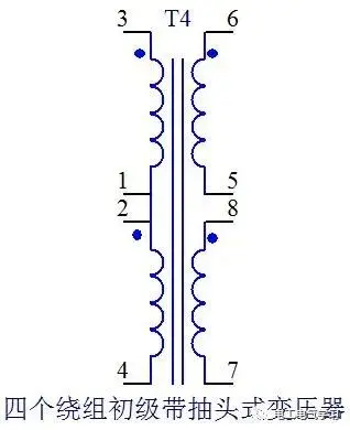
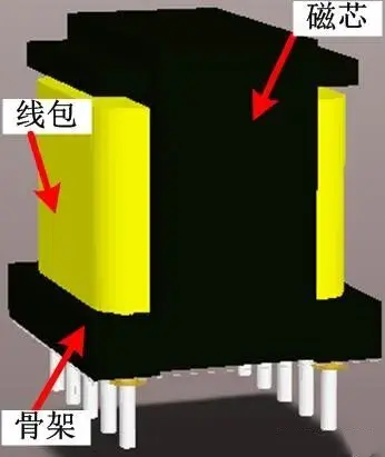
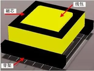
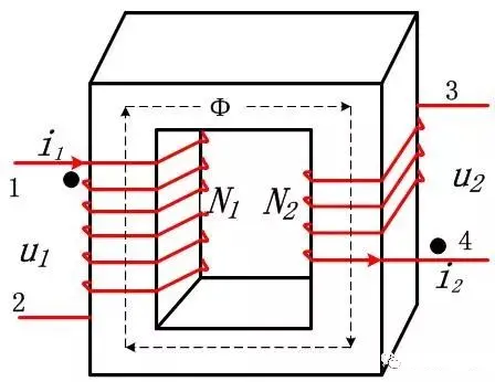
(1) Overview: A transformer is a coupled inductor consisting of two or more sets of coil windings (it does not store energy but transmits energy, see below). Since it is a device that works in a coupled manner, a high-permeability magnetic core is a necessary condition for establishing strong coupling. The primary completes the electromagnetism, and the magnetic field is “transmitted” along the high-permeability magnetic core. The secondary completes the magnetism to generate electricity, thereby providing energy to the actual circuit load. After such a conversion process, energy transmission is achieved while also completing the electrical isolation between the primary and secondary. The following is a common transformer winding form, and the two “||” represent the magnetic core.
Working principle of transformer:
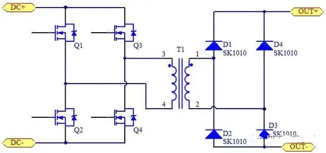
A transformer is an electrical device that works on the principle of electromagnetic induction. It can convert electrical energy between different voltage levels. A transformer mainly consists of two parts: the primary side (primary) and the secondary side (secondary).
The primary and secondary side
Primary side: The coil connected to the power supply, usually with a higher voltage.
Secondary side: The coil is connected to the load, usually with a lower voltage.
When the primary side passes AC, it generates a changing magnetic flux in the transformer’s core. According to Faraday’s law of electromagnetic induction, this changing magnetic flux generates an induced electromotive force on the secondary side.
Ideally, the efficiency of the transformer is 100%, that is, the input power is equal to the output power. However, in practical applications, due to copper losses (losses caused by coil resistance) and iron losses (core hysteresis and eddy current losses), the efficiency of the transformer is usually slightly lower than 100%.
Vertical transformer
The no-load state of the transformer, when there is no load on the secondary, disconnect the secondary from the load
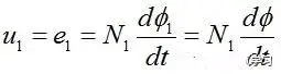
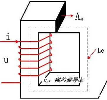
As long as it involves electromagnetism, you will inevitably have to apply Faraday’s law of electromagnetic induction. A voltage u1 is added to the primary of the transformer. According to the law of electromagnetic induction, the induced voltage of the primary coil is expressed as follows, that is, the induced electromotive force e1 is equal to the input voltage u1:
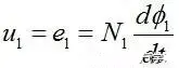
The current i1 caused by the primary coil generates a magnetic flux φ1 in the magnetic core. The current i1 is the excitation or exciting current, which is the excitation source for generating the magnetic field. The magnetic flux φ1 is also called the main magnetic flux.
The transformer is a magnetic flux transmission device with a high magnetic permeability magnetic closed core as the magnetic circuit, so in theory, the transformer is a fully coupled device with a coupling coefficient of k=1. The magnetic flux is generated by the primary coil (electromagnetic). Since the transformer shares the same magnetic core, the primary and secondary magnetic fluxes are the same, that is, φ1=φ12=φ (Ψ=N*φ is called flux linkage, φ12 represents the magnetic flux generated by coil N1 on coil N2. Because it is unloaded, the secondary coil 2 has no source of its magnetic flux), and the rate of change of the magnetic flux φ is also the same. The induced electromotive force of the primary and secondary are expressed as follows:
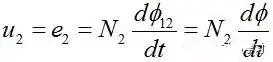
According to ② and ③, we can get formula ④

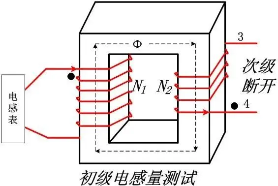
We usually measure the primary inductance L1 of the transformer.
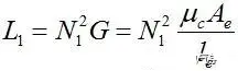
From formula ⑤, we can see that for any coil of the primary and secondary of the transformer, the permeance G is a constant, because the permeance is a constant of the magnetic core property.
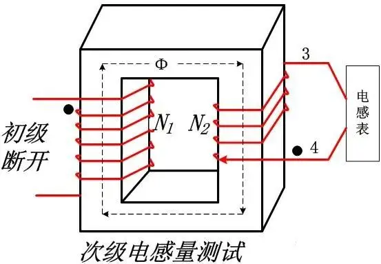
For the secondary coil, the inductance L2
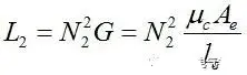
Combining ⑤ and ⑥, we get ⑦, that is, the square ratio of the turns ratio is the ratio of the primary and secondary inductances.

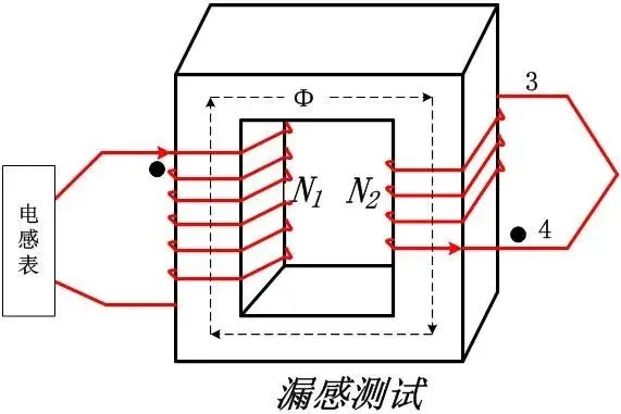
Therefore, when you measure the primary and secondary inductance of the transformer, you also get the turn ratio of the transformer. This is sometimes useful. For example, when you get a transformer, you don’t know the turns ratio of the transformer, but by measuring the inductance of the coil with an inductance meter, you can know the turns ratio of the transformer. Of course, when measuring the inductance, the coils must be disconnected from each other. If you measure the primary inductance and short-circuit the secondary coil, then what is measured is the leakage inductance of the transformer.
Load state of the transformer. When the secondary of the transformer is connected to the load, due to the load factor, the secondary voltage u2 and the load Z generate a current i22. The current i22 generates a magnetic motive force F2=i22*N2 in the secondary coil N2 (the principle of electromotive force in the circuit). The magnetic flux generated is φ22.
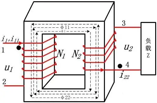
Do you remember Ohm’s law in the magnetic circuit? The quotient of the magnetic motive force and the magnetic resistance is the magnetic flux. The derivation of this formula is also very simple. The basic principle is Ampere’s circuit theorem. In formula ⑧, Rm is the magnetic resistance, and G is the magnetic permeance (there is a definition in the previous formula ⑤). This is a constant in the same magnetic core.
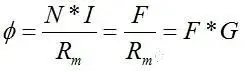
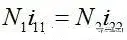
The magnetic flux φ22 caused by the load is in the opposite direction to the magnetic flux φ11 generated by the primary coil. This is what Lenz’s theorem tells us. In essence, the magnetic flux generated by the secondary coil must be balanced with the primary coil except for the excitation magnetic flux.
After loading, the primary magnetic flux is the sum of the previous no-load excitation magnetic flux and the magnetic flux caused by the load “φ1+φ11”. The excitation magnetic flux is a necessary condition for establishing electromagnetic conversion. At the same time, it can be seen that the primary current enters from the same-name terminal and the secondary current flows out from the same-name terminal, which just keeps the energy in and out and maintains the magnetic balance (it cannot accumulate, accumulation means that the transformer will saturate after a certain period)

Combining equation 9 with equation 8, we get

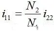
Formula ⑫ is called reflected current, which is the reflection of the secondary current to the primary caused by the load current. The larger the load current, the larger the reflected current.
Formula ④ shows that the transformer has a voltage conversion function from the primary to the secondary; Formula ⑪ shows that the transformer has a current conversion function from the secondary to the primary.
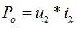
From the power perspective, output power
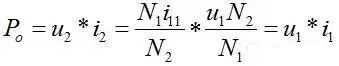
From the formula ⑭, we can get that the input power and output power are equal. The excitation current only provides the conditions for energy transmission. It is not necessary to store energy in the magnetic field. The transformer is an energy transmission device, not an energy storage device. In actual transformers, high magnetic permeability materials are used to increase the excitation inductance to reduce the excitation current. The purpose of reducing the excitation current is to reduce copper loss and magnetic loss.
Reflected impedance, when the output is loaded, the load takes energy through the transformer, and the input current will increase accordingly. Therefore, the equivalent input impedance of the transformer is as follows:
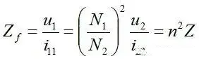
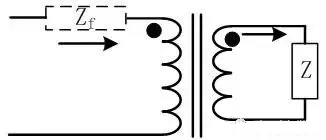
Reflected impedance is a circuit equivalent model. In the actual circuit, there is no resistor or other resistors in series, but the load does exist. Reflected impedance is the equivalent of a primary impedance caused by the load effect.
Finally, it should be emphasized that the transformer is an energy transmission component. Only the excitation current causes energy storage, which cannot be transmitted to the secondary side for use by the load. When the transformer is loaded, the secondary current, that is, the magnetomotive force generated by the load current, is the demagnetizing magnetomotive force. Excitation is the basis for ensuring energy transmission. Without it, the secondary voltage will no longer exist, and there is no energy transmission.