
Pole Mounted Transformer manufacturer
Utility-grade Single-Phase & Three-Phase overhead distribution transformers in Conventional and Completely Self-Protected (CSP) designs. Engineered for continuous outdoor service and compliant with IEEE C57.12.20, IEC 60076, CSA, and DOE efficiency mandates.
Capacity: 10 kVA – 333 kVA (Single-Phase) / 15 kVA – 500 kVA (Three-Phase)
Primary Voltage: 2.4 kV – 36 kV (GrdY / Delta)
Frequency: 50 Hz/60 Hz
Compliance: IEEE C57.12.20, IEC 60076, DOE 2016 & CSA C2.1 / C2.2
High-Reliability Pole Mounted Transformer Manufacturer
High-Reliability Pole Mounted Transformer Manufacturer
Engineered for continuous operation in severe overhead distribution environments, GE Transformer delivers premium conventional and Completely Self-Protected (CSP) transformers. Fully compliant with IEEE, IEC, and CSA standards, our units exceed global efficiency mandates while minimizing maintenance overhead and installation footprint.
Core Engineering Advantages:
- Integrated CSP Protection: Natively incorporates high-voltage surge arresters, low-voltage circuit breakers, and internal fuses. This 3-in-1 design eliminates external protective hardware and significantly reduces installation costs.
- Superior Mechanical Integrity: Features 100% external weld tracking, recessed tank bottoms, and uniform torque-tightened Nitrile (NBR) gaskets to guarantee a permanently sealed, leak-free structural enclosure.
- Advanced Core Design: Utilizes EPRI-recommended interlaced cores in premium Grain-Oriented Silicon or Amorphous steel, specifically engineered to resist low-side voltage surges and minimize no-load losses.
- Extreme Environment Ready: Tank surfaces exceed industry standards with optional ISO 12944 C5-M marine-grade anti-corrosion finishes. Compatible with standard mineral oil or FR3 biodegradable fluid for heightened fire safety.
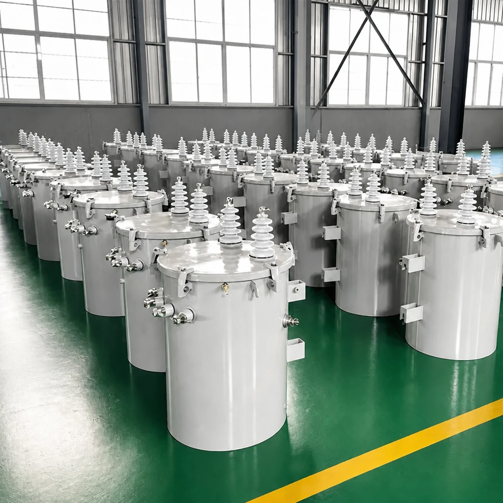
Pole Mounted Transformers

200 kVA pole mounted transformer
167 kVA pole mounted transformer
150 kVA pole mounted transformer
100 kVA pole mounted transformer
75 kVA pole mounted transformer
50 kVA pole mounted transformer
37.5 kVA pole mounted transformer
25 kVA pole mounted transformer
15 kVA pole mounted transformer
10 kVA pole mounted transformer
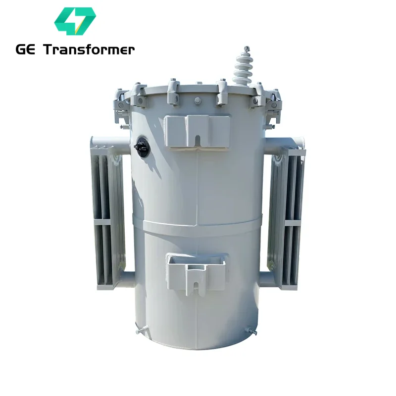
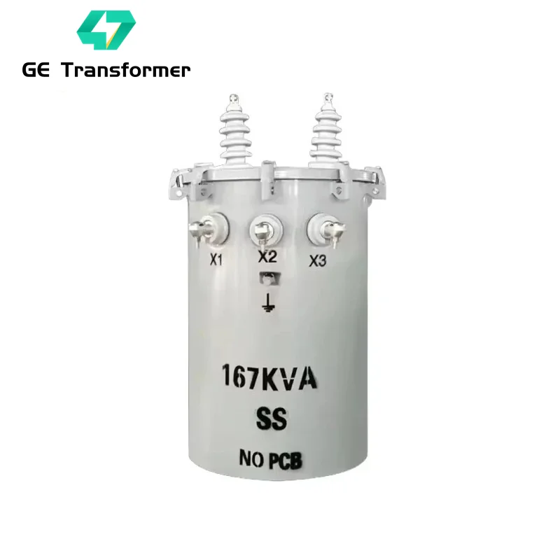
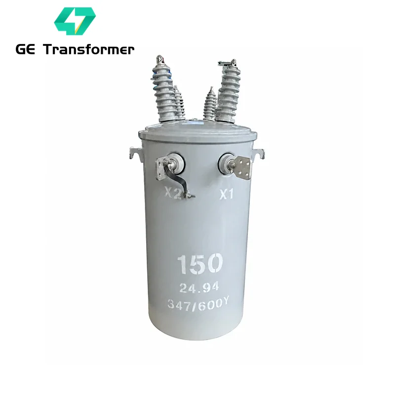
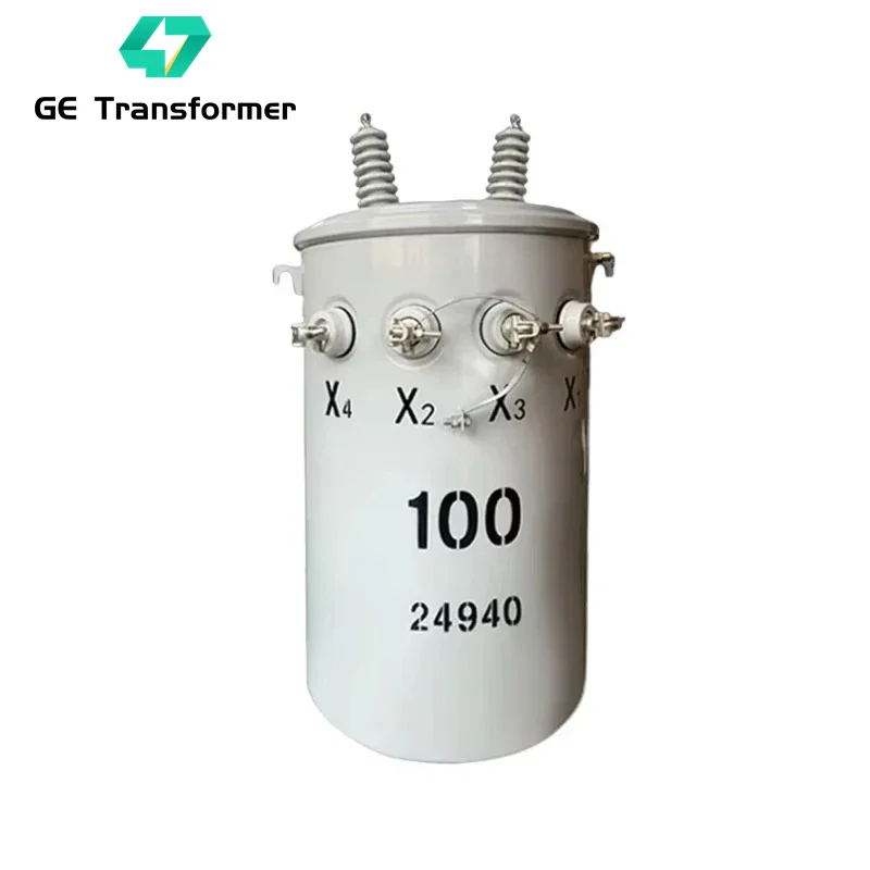
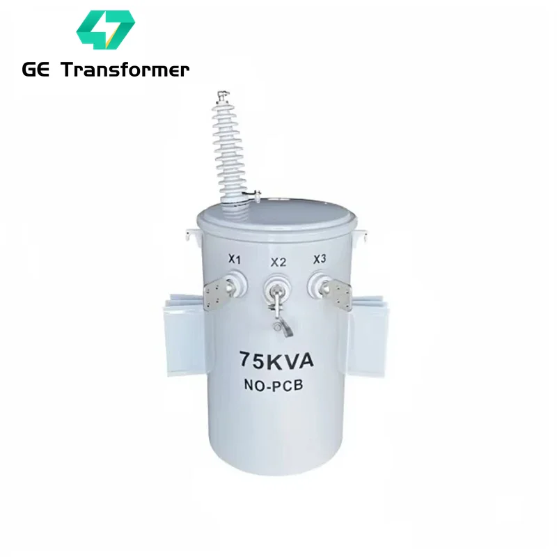
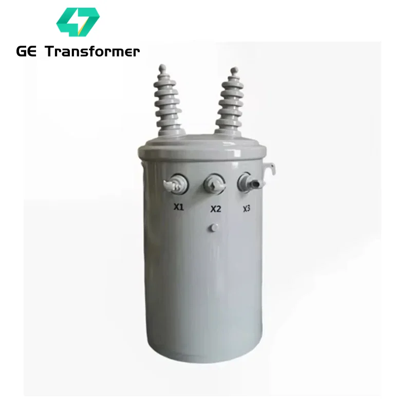
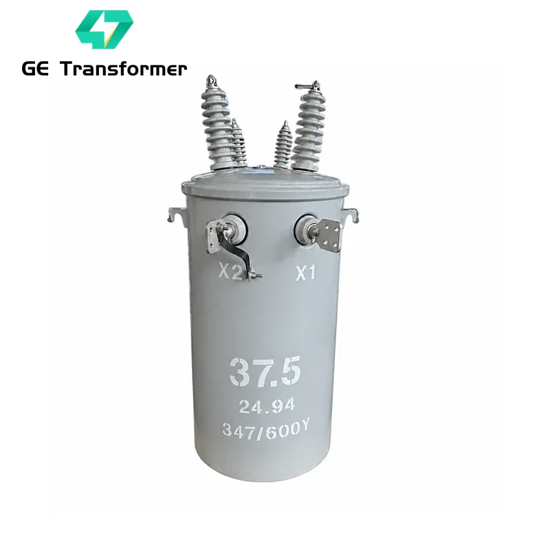
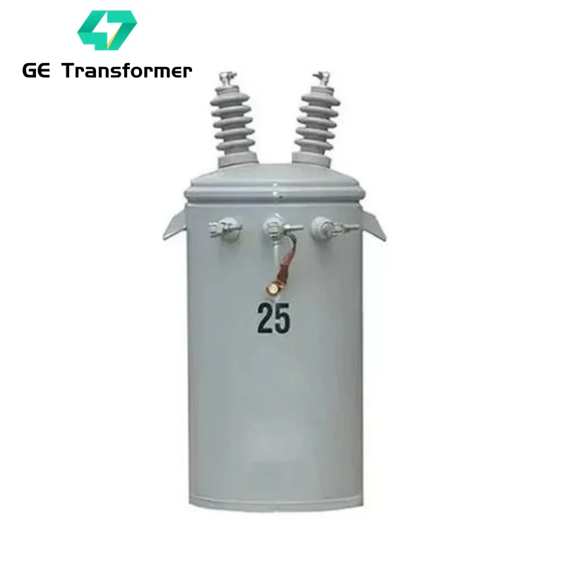
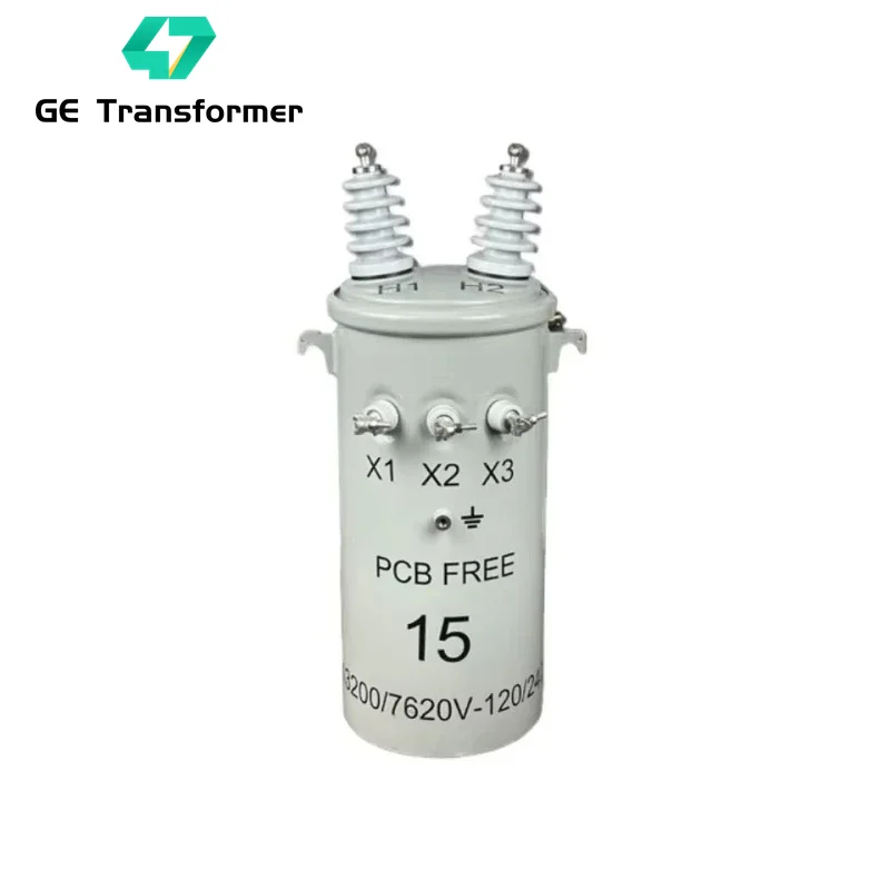
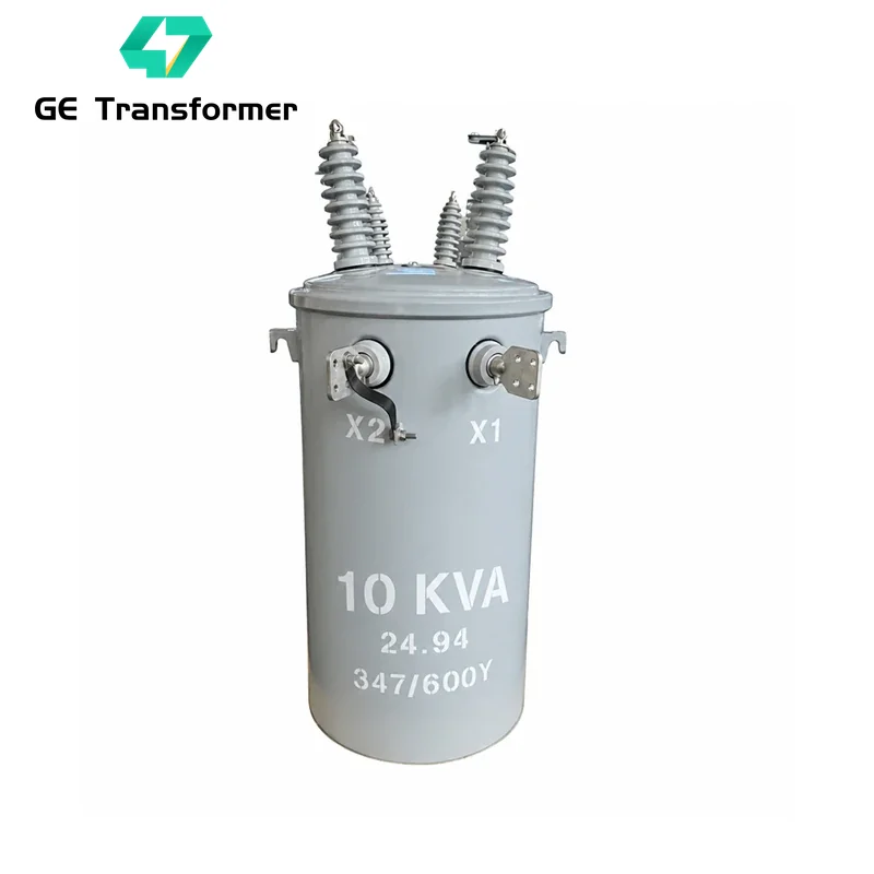
Pole Mounted Transformer Types (Conventional vs. CSP)
| Feature | Conventional Type | CSP (Self-Protected) Type |
|---|---|---|
| Surge Protection | External pole-mounted lightning arrester required | Tank-mounted primary HV surge arrester included |
| Overload & Secondary Fault | Relies on primary fuse coordination | Internal LV thermal-magnetic breaker with signal light & external reset handle |
| External Cutout Required | Yes (requires external expulsion fuse cutout) | No (built-in internal under-oil protective fuse link) |
| Typical Application | Urban & industrial feeders with existing protective cutouts (10–500 kVA) | Rural grids, high-lightning areas & residential lines (10–167 kVA) |
Pole Mounted Transformer Ratings
10 kVA, 15 kVA, 25 kVA, 37.5 kVA, 50 kVA, 75 kVA, 100 kVA, 150 kVA, 167 kVA, 200 kVA, 250 kVA, 333 kVA
2. Single-Phase Primary Voltage Ratings:
2400V, 7200V, 12470GrdY/7200V, 7620V, 13200GrdY/7620V, 7957V, 13800GrdY/7957V, 14400V, 24940GrdY/14400V, 19920V, 34500GrdY/19920V, 27600V (CSA Ontario)
3. Three-Phase Power Ratings:
15 kVA, 25 kVA, 45 kVA, 63 kVA, 100 kVA, 150 kVA, 200 kVA, 315 kVA, 400 kVA, 500 kVA
4. Three-Phase Primary Nominal Voltage:
11 kV, 13.8 kV, 15 kV, 20 kV, 22 kV, 33 kV, 34.5 kV, 36 kV
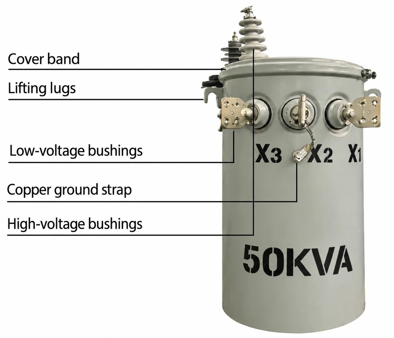
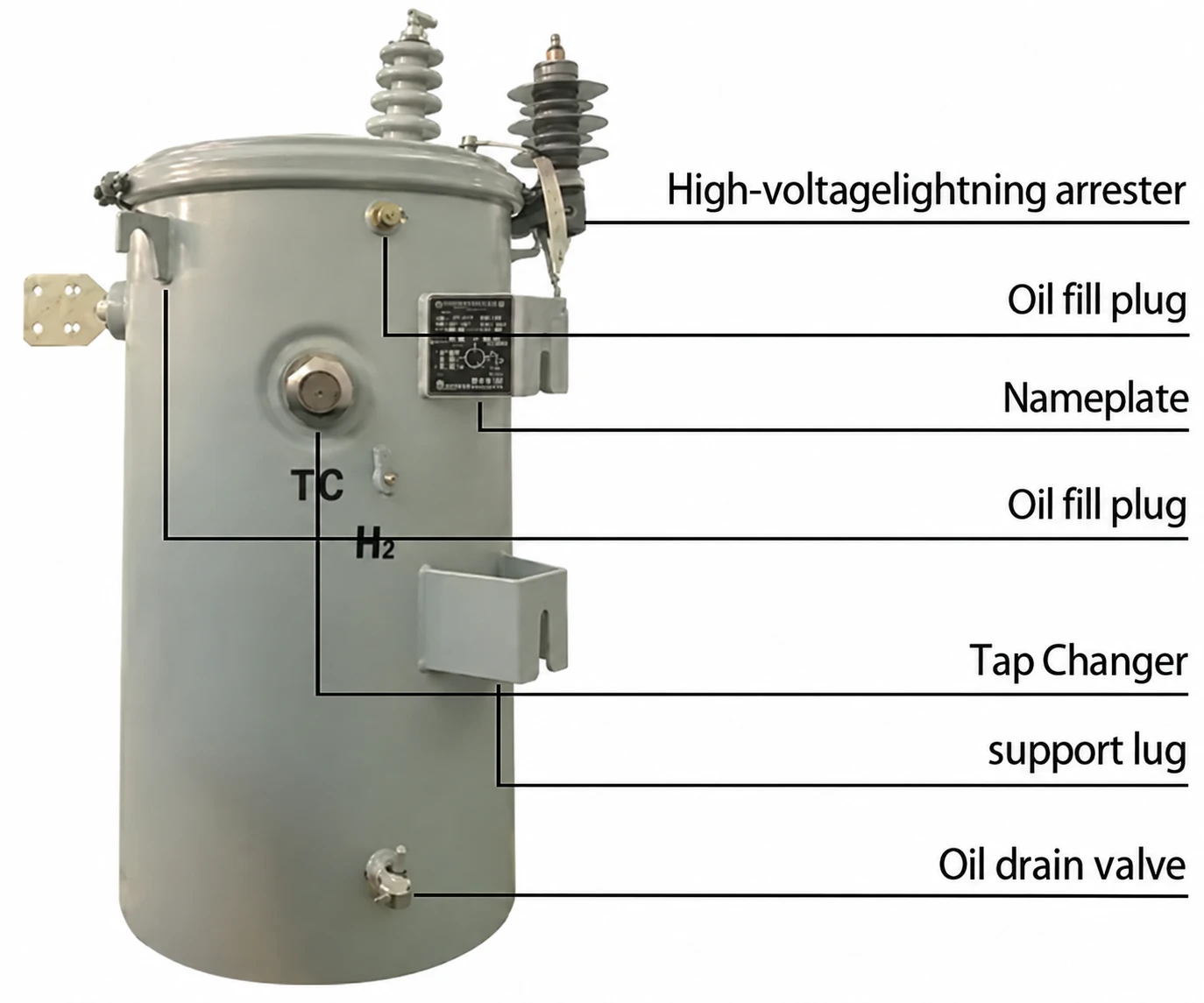
Pole Mounted Transformer Specifications (Dimensions & Weight)
| Power Rating | Width (mm) | Depth (mm) | Height (mm) | Total Weight (kg) |
|---|---|---|---|---|
| 10 kVA | 500 | 525 | 885 | 150 |
| 15 kVA | 550 | 550 | 915 | 190 |
| 25 kVA | 610 | 610 | 965 | 240 |
| 37.5 kVA | 660 | 660 | 1040 | 310 |
| 50 kVA | 690 | 690 | 1120 | 375 |
| 75 kVA | 760 | 760 | 1190 | 490 |
| 100 kVA | 810 | 810 | 1245 | 610 |
| 167 kVA | 890 | 890 | 1320 | 820 |
| 250 kVA | 1020 | 980 | 1390 | 1180 |
| 333 kVA | 1140 | 1060 | 1450 | 1550 |
Pole Mounted Transformer Technical Parameters
| No. | Item | Description / Parameter |
|---|---|---|
| 1 | Rated Power | Single-phase: 10 kVA to 333 kVA; Three-phase: 15 kVA to 500 kVA |
| 2 | Frequency | 50 Hz / 60 Hz |
| 3 | High Voltage | 2.4 kV, 4.16 kV, 7.2 kV, 7.62 kV, 7.97 kV, 10 kV, 11 kV, 12.47 kV, 13.2 kV, 13.8 kV, 14.4 kV, 19.92 kV, 20 kV, 22 kV, 24.94 kV, 33 kV, 34.5 kV, 36 kV |
| 4 | Low Voltage | 120/240 V, 240/480 V, 277/480Y V, 208Y/120 V, 400/230 V, 415/240 V, 600Y/347 V (or customer specified) |
| 5 | Connection Group | Ii0, Ii6 (Single-phase); Dyn11, Yyn0, Yzn11 (Three-phase) |
| 6 | Winding Material | Copper or Aluminum (customizable) |
| 7 | Cooling Type | ONAN (Mineral Oil) / KNAN (FR3 Natural Ester Fluid) |
| 8 | Rated Impedance Voltage | 1.5% – 4.5% (Single-phase); 4.0% – 6.0% (Three-phase) |
| 9 | Temperature Rise | 55°C / 65°C (Winding); 50°C / 60°C (Top Oil) |
| 10 | Altitude | ≤1000 m (Higher altitude engineering available upon request) |
| 11 | Ambient Temperature | -40°C to +45°C |
| 12 | Protection Level | IP54 / IP65 Hermetically Sealed Outdoor Tank |
| 13 | Noise Level | ≤48 dB to 58 dB (Compliant with NEMA TR-1) |
| 14 | Installation Type | Outdoor Pole-Mounted (Direct Pole Bolt or Crossarm Hanger) |
| 15 | Accessories | HV/LV Bushings, Pressure Relief Device, Tap Changer, Grounding Lug, Surge Arrester (CSP), LV Breaker (CSP) |
| 16 | Applicable Standards | IEEE C57.12.20, IEC 60076, CSA C2.1 / C2.2, DOE 2016, AS/NZS 60076 |
| 17 | Min. Order Quantity | 1 Set |
| 18 | Warranty | 24 Months (Extended warranty options available) |
| 19 | Delivery Time | 20 – 30 Days for Standard Specifications |
Single-Phase Pole Mounted Transformer Structural Features
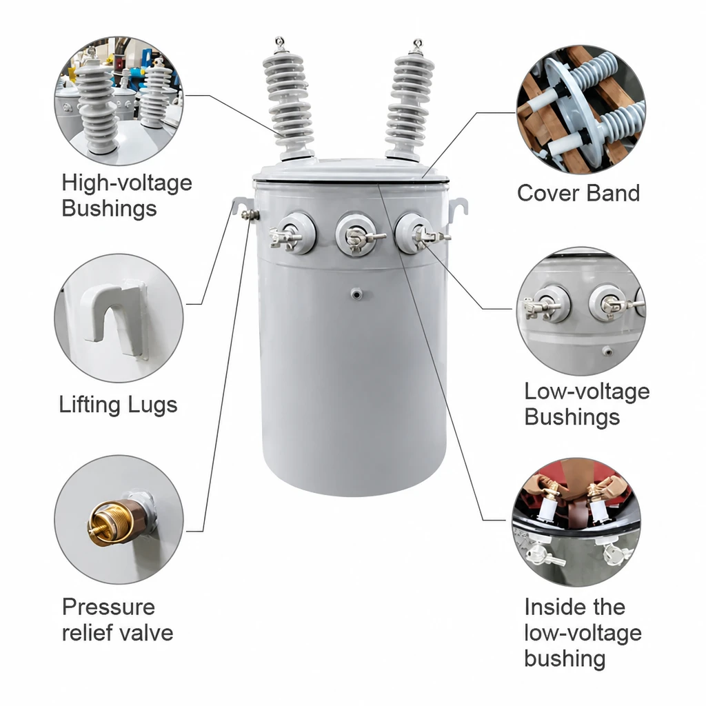
- 1. HV Porcelain Bushings with Ring / Eye-Bolt Terminals: Cover-mounted wet-process glazed porcelain bushings (single or dual HV) fitted with tin-plated bronze eye-bolt terminals suitable for both copper and aluminum overhead conductors.
- 2. Circular Sealed Tank Cover Structure: Roll-seamed circular tank cover structure provides uniform gasket compression, preventing moisture ingress and facilitating field maintenance.
- 3. Tin-Plated LV Bushings & Spade / Clamp Terminals: Tank-wall mounted porcelain or molded polymer low-voltage bushings with tin-plated copper/bronze clamp or NEMA spade terminals.
- 4. Self-Sealing Pressure Relief Device (PRD): Automatically vents excessive internal pressure during abnormal thermal or fault events and immediately reseals to keep the tank airtight.
- 5. ANSI-Compliant Top & Bottom Suspension Hooks: Heavy-duty top and bottom pole-mounting support lugs welded in strict compliance with ANSI/IEEE C57.12.20 and CSA C2.1 dimensions.
- 6. Tank Ring-Bolt Grounding Terminal: Corrosion-resistant bronze grounding ring-bolt connector welded near the tank base for reliable utility pole ground bonding.
Pole Mounted Transformer Accessories
CSP-Specific Attachments
- High-Voltage Surge Arrester: Tank-mounted metal-oxide varistor (MOV) lightning arrester protects windings against severe atmospheric voltage spikes.
- Internal Current-Limiting Fuse: Under-oil protective link fuse isolates the transformer from the primary distribution feeder in the event of an internal fault.
- Low-Voltage Circuit Breaker: Oil-immersed secondary breaker with an external operating handle and overload signal light to prevent thermal burnout.
Standard Fittings
- High-Voltage Bushings: Cover-mounted wet-process porcelain bushings.
- Low-Voltage Bushings: Sidewall-mounted porcelain or polymer bushings.
- Pressure Relief Device: Self-resealing mechanical brass pressure relief valve.
- Oil Fill & Drain Valves: Upper oil fill plug and bottom drain valve with sampling device.
- Heavy-Duty Tank & Cover: Seam-welded steel tank with recessed bottom.
- Lifting & Support Lugs: ANSI Type A, B, or C mounting brackets and lifting lugs.
- Internal Oil Level Indicator: Clearly marked internal oil level line at 25°C.
- Grounding Provisions & Nameplate: Tank earthing stud and laser-engraved stainless steel nameplate.
Optional Accessories
- Externally Operated Off-Circuit Tap Changer: De-energized rotary tap switch (±2×2.5% or custom steps).
- External Dual-Voltage Switch: Allows rapid primary voltage series-parallel changeover (e.g., 7.2 kV × 14.4 kV).
- Internal Fault Detector (IFD): Provides immediate visual external indication of internal tank overpressure.
- Dielectric Fluids: Standard ASTM mineral oil or biodegradable FR3 natural ester fluid.
- Comprehensive Monitoring Gauges: Dial thermometer, magnetic oil level gauge, and pressure-vacuum gauge.
- Wildlife Protectors: Polymer bird/animal guards installed on HV bushing terminals.
Pole Mounted Transformer FAT & QC
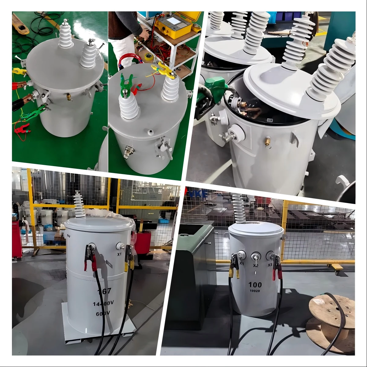
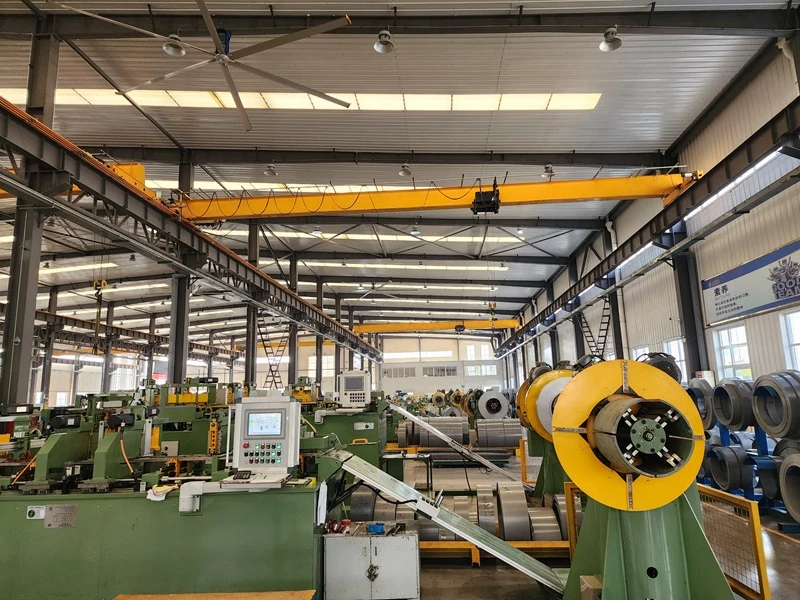
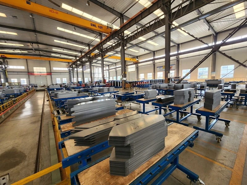
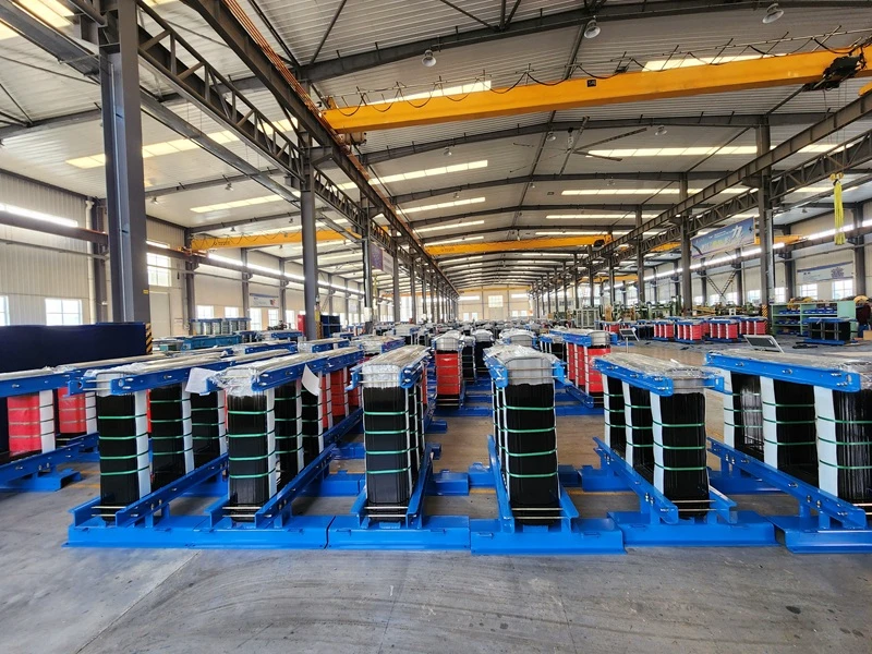
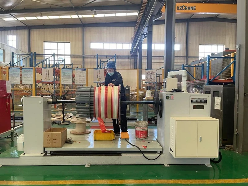
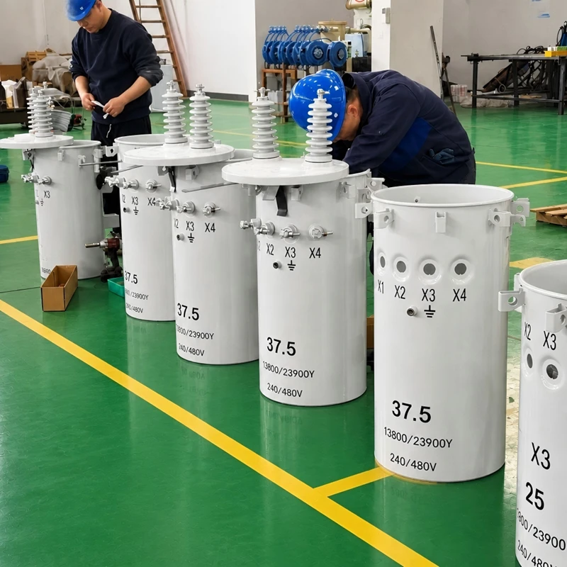
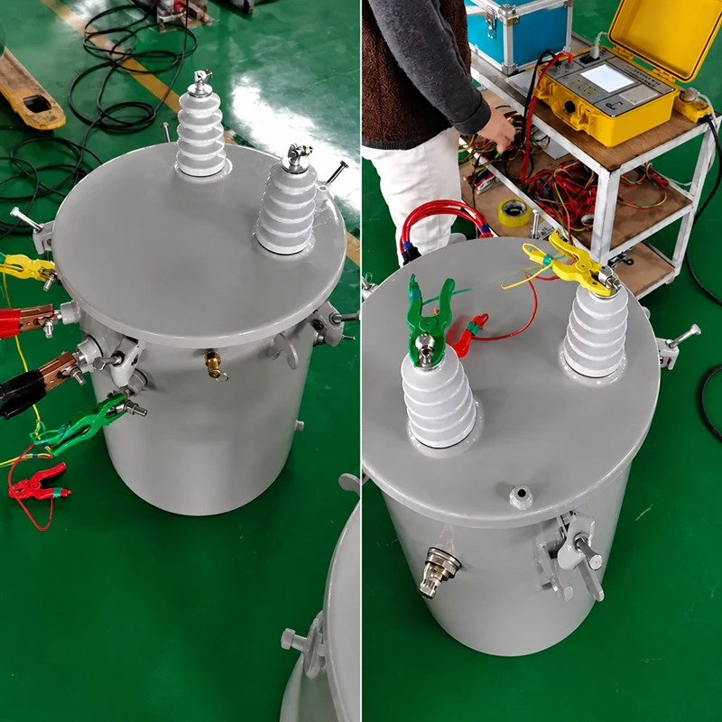
At GE Transformer, quality assurance is deeply integrated into our manufacturing process. Every single pole mounted transformer undergoes a stringent series of electrical, thermal, and mechanical diagnostics in our state-of-the-art testing facility before delivery.
All testing protocols strictly adhere to IEEE C57.12.90 and IEC 60076 standards. Upon completion, we provide a comprehensive, formally documented Certified Test Report (FAT) signed by our chief engineers, ensuring complete transparency and peace of mind for your project.
1. Routine Tests (Performed on 100% of Units)
Every unit is thoroughly validated against its design specifications to guarantee safe and efficient field operation.
Ratio, Polarity, and Phase Relation: Verifies the exact voltage ratio accuracy and ensures the correct vector group configuration.
Winding Resistance Measurement: Checks the integrity of all internal connections and winding performance.
Insulation Resistance Measurement (Megger Test): Evaluates the dielectric quality of the insulation system to effectively prevent electrical leakage.
No-Load Loss and Excitation Current: Measures the core’s energy efficiency and validates compliance with global DOE/CSA energy mandates.
Load Loss and Impedance Voltage (%): Determines the transformer’s efficiency and voltage regulation capabilities under full-load conditions.
Applied and Induced Potential Tests: High-voltage dielectric withstand tests to verify the insulation’s ability to endure operational electrical stresses.
Pressure and Leak Testing: Each sealed tank undergoes rigorous pressure and vacuum testing to ensure the structural integrity of welds and gaskets, guaranteeing a leak-free lifespan.
2. Type Tests & Optional Tests
To validate the fundamental engineering of specific design series or upon client request, we conduct advanced performance testing.
Full-Wave Lightning Impulse Test (BIL): Simulates lightning strikes to ensure the interlaced core and insulation can safely withstand extremely high-voltage transients.
Temperature-Rise Test: Operates the unit at maximum continuous load to confirm that thermal limits (e.g., 55°C / 65°C rise) are strictly maintained.
Sound Level Test: Verifies that operational acoustic emissions meet low-noise regulatory standards for urban or residential deployment.
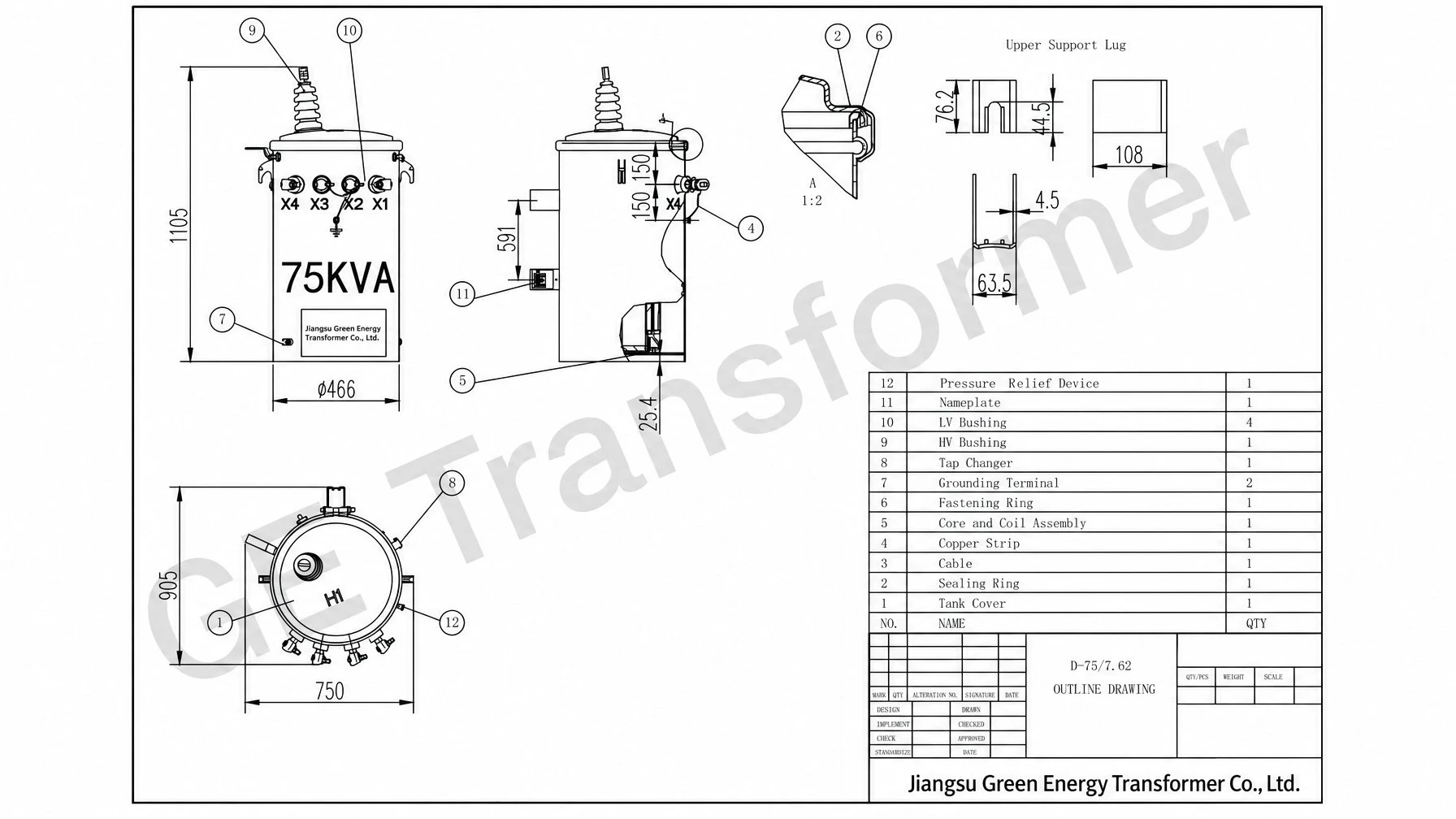
Pole Mounted Transformer Drawing
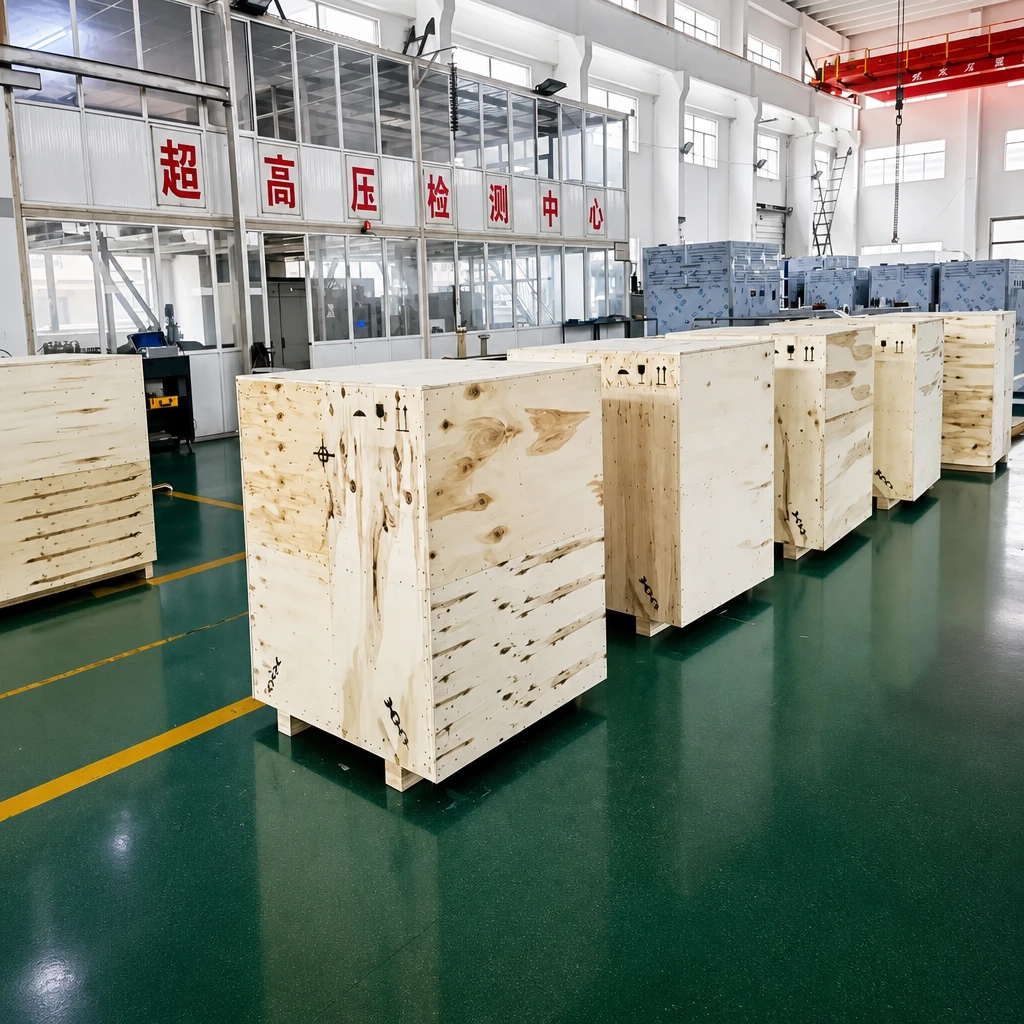
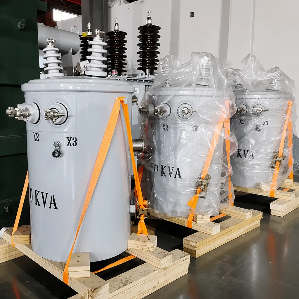
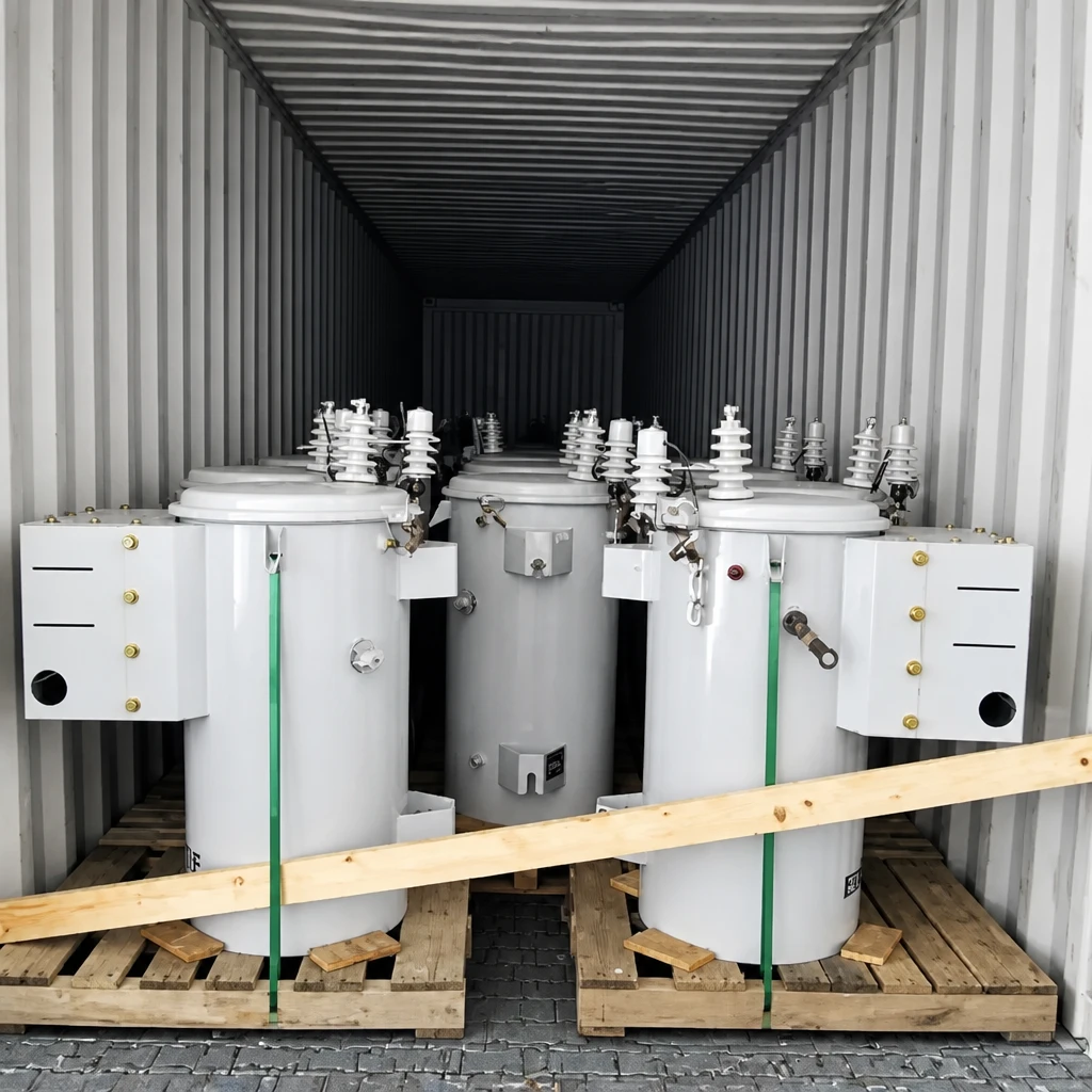
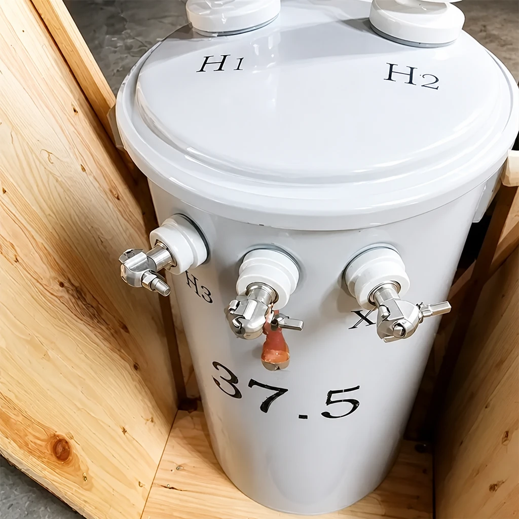
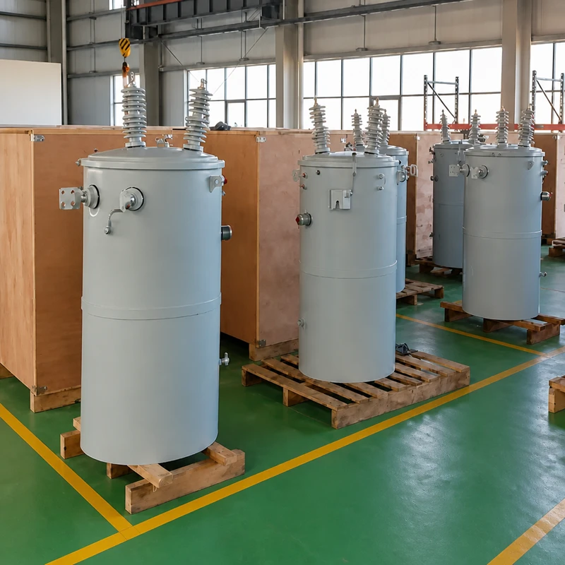
Pole Mounted Transformer Packaging and Shipment
Why Choose GE Transformer
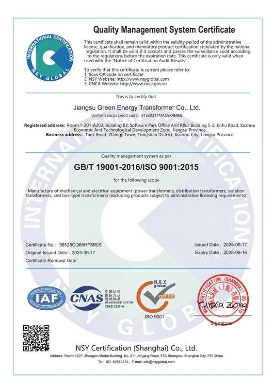
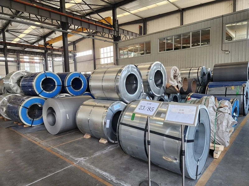
Quality Control: Quality is a core value of GE Transformer. We conduct Factory Acceptance Testing (FAT), type testing, and third-party inspections to ensure superior quality. We strictly adhere to the ISO 9001 quality management system, committed to providing our customers with the highest quality products.
Professional Team: Our team comprises highly skilled professionals dedicated to responding quickly to customer needs. All GE Transformer team members receive systematic training and continuously improve their capabilities through rigorous quality standards and practices. Our commitment to customer service, product innovation, engineering excellence, and social and environmental responsibility makes us a trusted partner in the global power industry.
Certifications
- ISO9001:2015
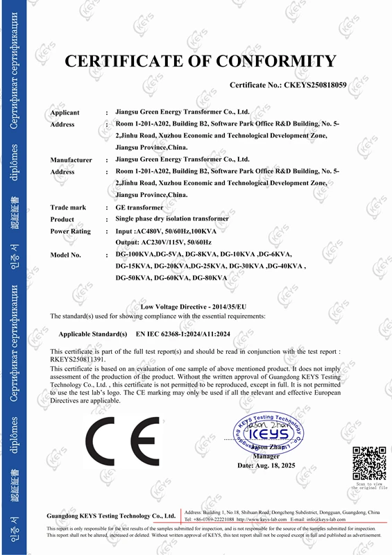
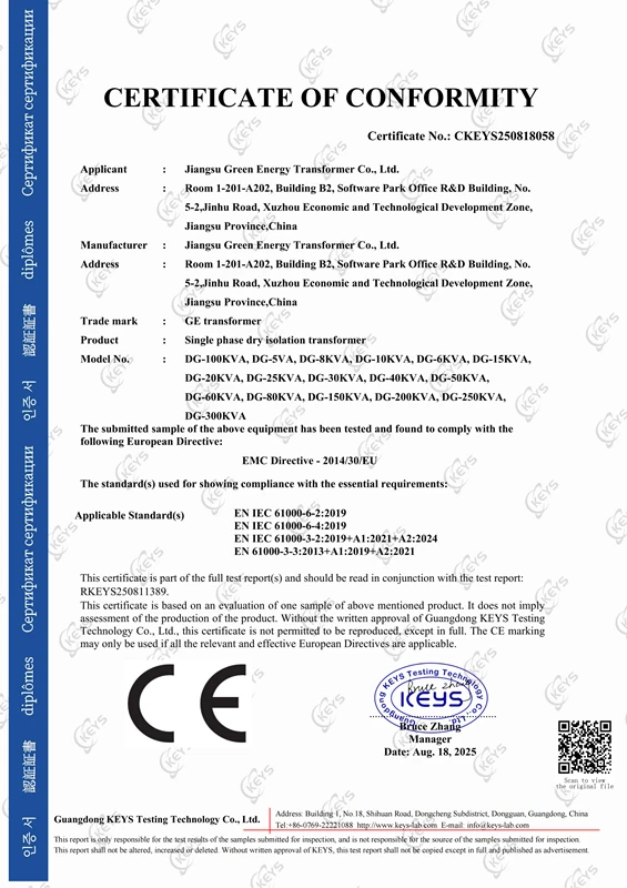
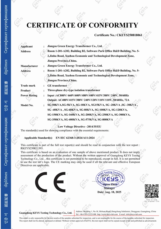
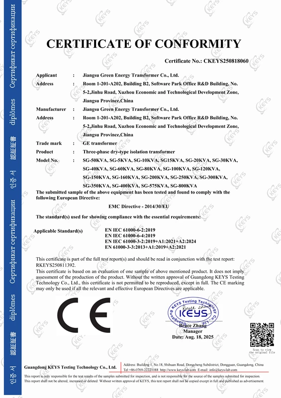
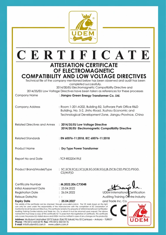
- CE Certifications:
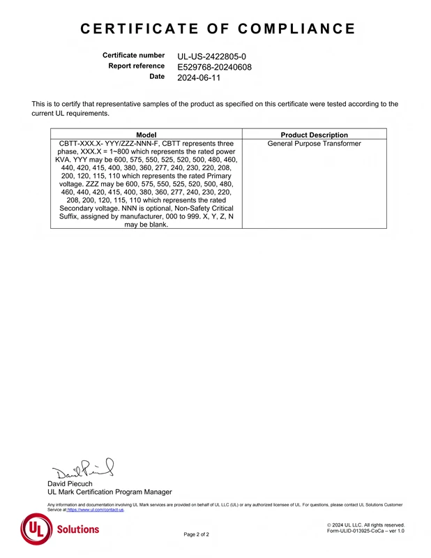
- UL Certifications:
- CSA Certification:
- CNAS Certification:
Competitive Market Pricing:Leveraging years of industry experience, GE Transformer integrates high-quality resources across R&D, production, procurement, transportation, and service, achieving effective cost control.
Fast Delivery: Strong production capacity, multiple freight partners, and a professional pre-sales and after-sales team, adhering to the “customer first” philosophy, provide customers with fast delivery and usage services.
FAQ
1. What is the main difference between a conventional and a Completely Self-Protected (CSP) pole mounted transformer?
A conventional transformer requires external pole-mounted protective devices, such as drop-out fuses and external surge arresters. A Completely Self-Protected (CSP) transformer natively integrates high-voltage surge arresters, internal current-limiting fuses, and a low-voltage secondary circuit breaker directly within or on the tank. This highly integrated design eliminates the need for external cut-outs, significantly reducing installation time, footprint, and overall deployment costs.
2. How do GE Transformer units ensure longevity in highly corrosive coastal or marine environments?
For projects located in areas with high salt spray or extreme humidity, we upgrade the standard tank finishing process to an ISO 12944 C5-M marine-grade anti-corrosion coating system. Combined with our 100% continuous external weld tracking, recessed tank bottoms to prevent moisture accumulation, and premium Nitrile (NBR) gaskets, our transformers are engineered to deliver a leak-free and rust-resistant lifespan even in the most aggressive atmospheric conditions.
3. Are your pole mounted transformers compatible with environmentally friendly dielectric fluids?
Yes. While our standard units are filled with premium electrical-grade mineral oil, we fully support the use of biodegradable ester fluids, such as FR3 fluid, as an optional accessory upgrade. FR3 fluid significantly raises the flash point for enhanced fire safety, extends the operational life of the insulation paper, and provides superior environmental compliance for eco-sensitive installation sites.
4. Can you customize the impedance, load losses, and no-load losses to meet our specific local utility standards?
Absolutely. GE Transformer operates a fully integrated engineering and manufacturing facility. Our technical team can optimize the core-and-coil design—utilizing high-grade grain-oriented silicon steel or amorphous metal—to precisely match your required short-circuit impedance and efficiency metrics. We routinely design units that exceed stringent global efficiency mandates, including the U.S. DOE 2016 and CSA standards.
5. Do you offer dual-voltage configurations for grids undergoing voltage upgrades?
Yes, we frequently design dual-voltage pole mounted transformers equipped with an external dual-voltage switch. This allows utility personnel to easily toggle between two primary voltage classes (e.g., from 12.47 kV to 24.94 kV) without opening the transformer tank or performing internal rewiring. It is an ideal solution for future-proofing grid infrastructure during systemic voltage transitions.
6. What testing documentation is provided upon delivery of the transformers?
Every transformer that leaves our facility undergoes rigorous routine testing in accordance with IEEE C57.12.90 and IEC 60076 standards. Upon dispatch, we provide a comprehensive Certified Test Report (Factory Acceptance Test – FAT) signed by our chief engineers. This official documentation details the results of ratio, winding resistance, dielectric withstand, and loss measurements, serving as a guarantee of quality and compliance for your project records.
7. What is the typical lead time for a bulk utility-scale order?
Standard production lead times typically range from 4 to 6 weeks after the final approval of the technical drawings, depending on the specific capacity, voltage class, and order volume. For urgent utility projects or customized designs requiring specialized optional accessories, our project management team will provide a precise, transparent manufacturing schedule during the quotation phase.


