Transformer Sizing Chart and Worked Examples for Single-Phase and Three-Phase Loads
A transformer selected from the wrong current or voltage can leave your project with overheated windings, voltage dips or a replacement order. This guide helps you establish design demand, calculate kVA and check the available rating against individual winding loads. Start with the data sheet below, then follow the example that matches your installation.
You can use this guide in three ways. If your load is single-phase, start with Section 2. If it is a balanced three-phase load, use Section 3. If the transformer also supplies lighting, sockets or other single-phase circuits, read Section 4 before accepting the total kVA.
A useful sizing worksheet shows where every number came from. Keep the equipment nameplate, measurement or load schedule beside the calculation so your supplier can follow it and ask focused questions.
Already have a load schedule?
Send your voltage, phase, load schedule and site conditions to GE Transformer for a preliminary selection review and quotation. For a replacement, include a readable nameplate photo and the existing connection diagram.
Send your transformer requirements
1. Collect the load data before calculating
Voltage, phase, current, kW/kVA, duty cycle and power factor
Record the supply and load sides separately. A load drawing 300 A at 400 V has a different kVA requirement from one drawing 300 A at 11 kV. Each calculation must use quantities from the same side of the transformer.
For a 400/230 V wye system, 400 V is measured between two phases and about 230 V between a phase and neutral. Write “400 V line-to-line” in the worksheet. That small label prevents a common error when someone else checks your figures later.
| Input | What to record | What it changes |
| Voltage and phase | Primary and secondary voltage, line-to-line or line-to-neutral, single-phase or three-phase, frequency | Formula, ratio and winding connection |
| Load quantity | RMS current, electrical input kW and true PF, or nameplate kVA | Base apparent power |
| Operating profile | Simultaneous operation, peak magnitude and duration, duty cycle, starts per hour | Design demand and transient checks |
| Load character | Motors, converters, phase allocation and harmonic spectrum where available | Starting voltage dip, winding and neutral heating |
| Site and growth | Ambient profile, altitude, enclosure, cooling and documented future loads | Usable rating at the installation |
Use electrical input kW for motors. If only shaft output is known, obtain motor efficiency before converting to electrical input. For nonlinear loads, use true power factor with RMS measurements. Displacement power factor alone can miss distortion effects.
If a meter report shows 45 kW at 0.90 true PF, the load needs 50 kVA. If it already shows 50 kVA, that is your starting apparent power. Both reports describe the same operating point. Keep the date and operating state with the reading.
For winding relationships, see our three-phase transformer guide. Confirm the actual nameplate frequency, even when the catalogue offers 50 Hz and 60 Hz variants.
Connected load versus design demand
Connected load is the sum of installed equipment ratings. Design demand represents the coincident load you expect the transformer to supply, based on the operating schedule and applicable project rules. Keep the original connected-load total and the reason for each demand adjustment in the worksheet.
A plant with two interlocked pumps may operate one at a time. A changeover overlap or test mode may briefly operate both. Capture those operating states before applying a demand factor. At a new site, document the assumed sequence. At an existing site, record the measurement interval and whether it captured the relevant production and seasonal peaks.
For example, two 20 kVA pumps have 40 kVA of connected load. If their controls allow only one pump to run at a time, their running contribution may be 20 kVA. The engineer still needs to check the starting event and any overlap during transfer. Record the interlock assumption so a later controls change triggers a review.
2. Calculate single-phase transformer kVA
Formula and unit check
S (kVA) = V × I ÷ 1,000
S (kVA) = electrical input kW ÷ PF
I (A) = S (kVA) × 1,000 ÷ V
Use volts, amps and dimensionless PF. For example, 0.24 kV must be entered as 240 V when using the first equation. If you already know load kVA, use it directly. Reapplying a PF divisor would overstate that load.
For a 120/240 V split-phase transformer, check each 120 V half-winding and the neutral. Multiplying 240 V by a single measured line current represents total kVA only when the loading supports that assumption.
Worked example with selection of an available rating
Assume a single-phase utility service with a specified 240 V secondary supplies 60 kW of coincident electrical input at 0.90 PF. A documented expansion adds another 12 kW at the same PF and operating time. These are illustrative inputs for a new project.
| Step | Result | Selection consequence |
| Present demand | 60 ÷ 0.90 = 66.67 kVA | Establish the initial load |
| Design demand with expansion | (60 + 12) ÷ 0.90 = 80.00 kVA | Growth adds 13.33 kVA |
| Design secondary current | 80 × 1,000 ÷ 240 = 333.33 A | Record for downstream design |
| Catalogue candidate | 100 kVA | Confirm the voltage pair and site duty in the quotation |
| Candidate rated secondary current | 100 × 1,000 ÷ 240 = 416.67 A | 80 kVA uses 80% of nominal capacity under the stated conditions |
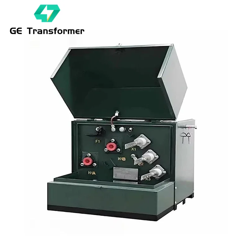
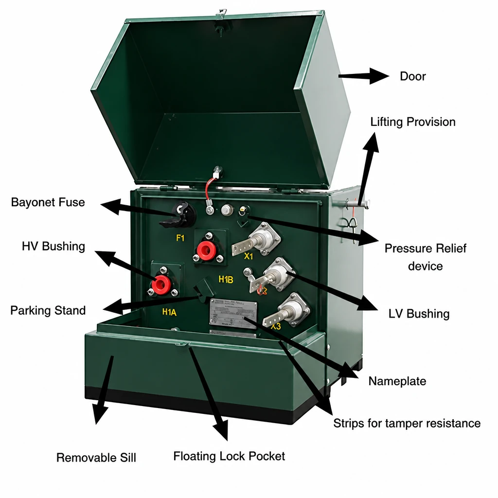
A 100 kVA single-phase pad-mounted transformer is a catalogue candidate for review. The resulting 80% loading comes from this example’s load and chosen rating. Your project may need a different reserve after starting, environment and duty are checked. Confirm the primary connection, insulation level, taps and secondary terminal arrangement with the utility.
In practical terms, this selection has 20 kVA of nominal capacity left after the planned expansion. That is 25% more than the 80 kVA design demand, while the design demand uses 80% of the 100 kVA nameplate. Those percentages use different denominators. Label which one you mean when comparing quotations.
3. Calculate balanced three-phase kVA
Line-to-line voltage and line current formula
S (kVA) = √3 × VLL × IL ÷ 1,000
IL (A) = S (kVA) × 1,000 ÷ (√3 × VLL)
VLL is line-to-line voltage and IL is line current on the same side. The formula assumes balanced loading. Using line-to-neutral voltage with this equation understates kVA by a factor of √3 on a balanced wye system. For a balanced wye load, the equivalent expression is S = 3 × VLN × I ÷ 1,000.
Confirm the winding configuration for a three-phase pad-mounted transformer. The total rating alone does not identify whether the installation has a usable neutral.
Worked example and full-load current check
Consider an 11 kV supply and a 400 V, 50 Hz balanced secondary load drawing 500 A. The load schedule identifies a further 50 A of simultaneous balanced expansion. No other growth allowance is assumed.
| Step | Calculation | Result |
| Present demand | √3 × 400 × 500 ÷ 1,000 | 346.41 kVA |
| Expansion demand | √3 × 400 × 50 ÷ 1,000 | 34.64 kVA |
| Design demand | √3 × 400 × 550 ÷ 1,000 | 381.05 kVA |
| Catalogue candidate | 400 kVA in the specified MV/LV series | 18.95 kVA nominal headroom |
| Secondary rated current | 400,000 ÷ (√3 × 400) | 577.35 A |
| Primary rated current | 400,000 ÷ (√3 × 11,000) | 20.99 A |
The design load occupies 95.26% of the candidate’s nominal rating. Keep 400 kVA as a preliminary candidate only if it supplies at least 381.05 kVA under actual site conditions and passes starting and system checks. A larger rating may be needed if the confirmed operating conditions reduce usable capacity.
The 400 kVA candidate leaves only 27.35 A between the 550 A design demand and its 577.35 A rated secondary current. That makes the site review important. Ask the supplier whether the unit can carry the design demand in your enclosure and ambient conditions. If it cannot, compare a larger available rating or an appropriate cooling design and repeat the system checks.
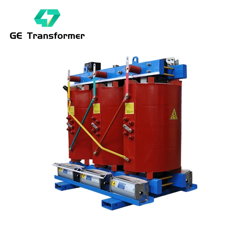
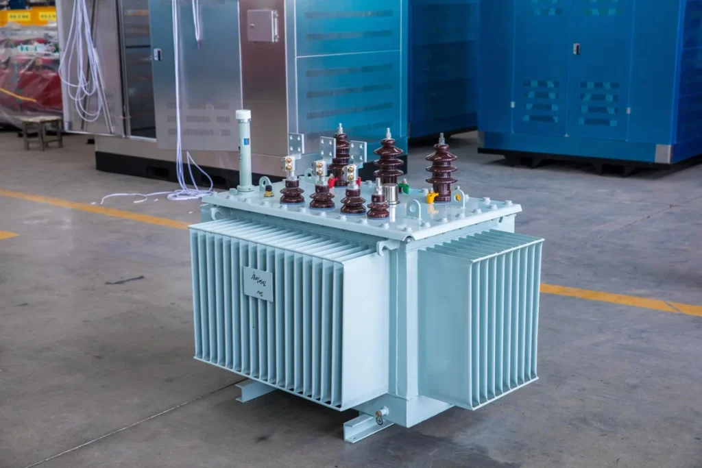
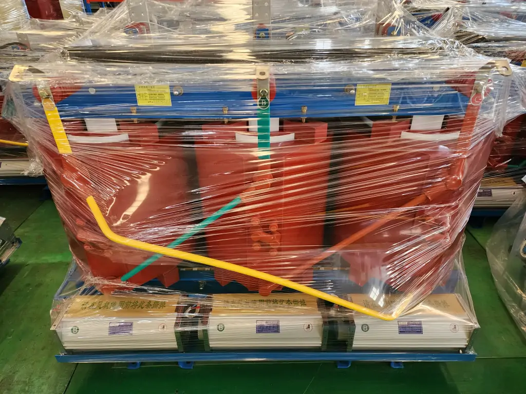
Review the available ratings in the 11 kV class cast resin distribution transformer series or the oil-immersed distribution transformer series. Ask the supplier to confirm voltage, cooling and impedance for the offered design.
Does your shortlist leave enough capacity?
Send the calculation and the operating conditions. Our engineering team can review the candidate rating and identify the additional data needed for motors, converters or unusual site conditions.
4. Check mixed and unbalanced loads
Per-phase worksheet and neutral considerations
For a four-wire wye secondary, allocate line-to-neutral loads to their actual phases. The following simplified example assumes 230 V line-to-neutral, linear resistive loads and a transformer with three equal secondary winding capacities. The balanced three-phase load contributes 10 kVA to each phase.
| Load allocation | Phase A kVA | Phase B kVA | Phase C kVA |
| Balanced three-phase load | 10 | 10 | 10 |
| Additional line-to-neutral loads | 30 | 5 | 5 |
| Phase total | 40 | 15 | 15 |
| Phase current at 230 V | 173.91 A | 65.22 A | 65.22 A |
The total is 70 kVA. Yet a nominal 100 kVA unit with equal phase capacities would allocate about 33.33 kVA per phase. Phase A needs 40 kVA, exceeding that preliminary winding-capacity screen. For this assumed arrangement, 3 × 40 = 120 kVA is the initial balanced-nameplate capacity screen before selecting an available rating.
Redistributing the single-phase loads can change that result. Verify manufacturer unbalance limits, individual winding ratings and the neutral arrangement before choosing the equipment. Line-to-line single-phase loads, delta windings, open-delta banks and unequal winding designs require connection-specific current calculations.
Here is why the phase check changes the decision. Moving 15 kVA of suitable single-phase circuits from A to B and 10 kVA from A to C would change the allocation to 15/30/25 kVA. Total demand remains 70 kVA, but each phase is now below the preliminary 33.33 kVA limit of the assumed 100 kVA unit. An electrical designer must confirm that the circuits can be redistributed and that the new operating pattern remains acceptable.
Think of the three windings as separate lanes with their own current limits. Spare room on phases B and C does not automatically relieve the overloaded winding on A. Before buying a larger transformer, check whether a practical phase redistribution solves the problem.
At the fundamental frequency, this resistive example gives neutral current of about 108.70 A from the vector sum of phase currents. Neutral current is not generally found by adding current magnitudes. With nonlinear loads, triplen harmonics can add in the neutral even when fundamental phase currents are balanced. Obtain harmonic and neutral-current data for final design.
Motor starting and nonlinear loads
For motors, collect the starting current, starter type, acceleration time, starts per hour, source impedance and acceptable voltage dip. Compare the predicted dip at the running equipment terminals. Transformer energisation inrush needs a separate protection-coordination check.
A 55 kW motor nameplate alone is not enough to decide how much starting duty the transformer must support. A directly started motor, a soft starter and a VFD can present different demands. Send the starter data and the other loads that will remain online during the start, especially equipment that may trip during a voltage dip.For VFDs, UPS systems and rectifiers, collect true PF, RMS current and the harmonic spectrum or manufacturer duty data. A K-factor-rated transformer may address harmonic heating. A harmonic mitigating transformer has a different system role that depends on its design and load connections. Confirm the actual application before specifying either.
5. Build a sizing chart that can be audited
Inputs, intermediate values and selected catalogue rating
The chart below gives calculated full-load current for stated voltage and phase combinations. It compares arithmetic at each rating. Confirm that the chosen product family offers the required voltage and kVA combination.
For example, the 100 kVA row at 400 V three-phase gives 144.3 A per line. If your balanced design demand is 130 A, the current comparison passes an initial screen. You still need to confirm the voltage pair, load profile and site conditions. When using this chart for a split-phase or unbalanced system, return to the winding checks above.
| Rating kVA | 240 V single-phase A | 400 V three-phase A | 415 V three-phase A | 480 V three-phase A |
| 25 | 104.2 | 36.1 | 34.8 | 30.1 |
| 50 | 208.3 | 72.2 | 69.6 | 60.1 |
| 75 | 312.5 | 108.3 | 104.3 | 90.2 |
| 100 | 416.7 | 144.3 | 139.1 | 120.3 |
| 150 | 625.0 | 216.5 | 208.7 | 180.4 |
| 250 | 1041.7 | 360.8 | 347.8 | 300.7 |
| 315 | 1312.5 | 454.7 | 438.2 | 378.9 |
| 400 | 1666.7 | 577.4 | 556.5 | 481.1 |
| 500 | 2083.3 | 721.7 | 695.6 | 601.4 |
| 630 | 2625.0 | 909.3 | 876.5 | 757.8 |
| 1000 | 4166.7 | 1443.4 | 1391.2 | 1202.8 |
Values are rounded to one decimal place from the formulas above. The three-phase columns assume balanced total kVA. The 240 V column represents a single-phase load across 240 V.
A project worksheet should keep the calculation trail beside the candidate selection.
| Record | Single-phase example | Three-phase example |
| Source data | 60 kW, 0.90 PF, 240 V | 500 A, 400 V line-to-line |
| Design basis | 12 kW simultaneous expansion at 0.90 PF | 50 A simultaneous balanced expansion |
| Design kVA | 80.00 | 381.05 |
| Catalogue candidate | 100 kVA single-phase | 400 kVA three-phase |
| Rated secondary current | 416.67 A | 577.35 A |
| Open checks | Utility interface, half-winding loading if applicable, site duty | Starting, phase balance, site duty, impedance and system studies |
Document assumptions and engineer review
Give the worksheet a revision, date and named reviewer. Attach the load schedule or measurement report, identify its operating state and record demand factors, PF assumptions, expansion and supplier catalogue revision. Keep the offered rating distinct from capacity confirmed for your site.
For industrial manufacturing projects, review the production sequence. For BESS projects, review charging and discharging duties with converter data. Missing inputs should appear as unresolved items before purchase approval.
6. Account for future growth and site conditions
Expansion, ambient, altitude and cooling
Add identifiable future loads with their operating schedules. If the owner requests a percentage reserve, record what the percentage applies to and why it is required. Avoid counting the same planned expansion both as a named load and as a growth allowance.
Ask for usable capacity at the specified ambient profile, elevation, enclosure and cooling condition. For a dual cooling rating, record the natural and forced cooling capacities and the expected duty if fans fail. Use the supplier’s project-specific design or derating guidance.
Be specific when describing a hot site. “Outdoor in the Middle East” gives less design information than the maximum ambient, daily average and enclosure arrangement from the project specification. The same applies to altitude and coastal exposure. Clear conditions let suppliers quote on a comparable basis.
| Market or site | Information to confirm |
| Middle East and other hot sites | Maximum and average ambient, sun exposure and dust or sand where applicable |
| Southeast Asia and coastal installations | Humidity, condensation, salt exposure and flood elevation where applicable |
| Australia and New Zealand | Applicable AS/NZS 60076 requirements and network acceptance details |
| North America | Actual frequency and voltage, applicable IEEE or CSA product requirements and utility interfaces |
| Africa, South America and Eastern Europe | Country and utility requirements, actual voltage and frequency, altitude and any islanded-source duty |
For remote sites, our island and remote power solutions provide application context. Supply the actual source and load data with your RFQ.
Separate transformer sizing from conductor/protection design
The kVA calculation establishes a capacity candidate. Conductor selection also requires installation method, temperature, grouping, voltage drop and applicable rules. Protection design must check transformer energisation, fault level, interruption and withstand duties, selectivity and local requirements.
A transformer rated at 577 A secondary does not by itself specify a 577 A protective device. Send the offered impedance, connection diagram, tap data and inrush information to the project electrical designer. Confirm applicable IEC 60076-1, IEEE C57.12.00 or AS/NZS 60076.1 requirements for equipment within their respective scopes.
Five items to send with your RFQ
| Item | Complete or attach |
| 1. Project | Country, utility, application, quantity and required date ___ |
| 2. Electrical system | Primary and secondary voltage, phase, Hz, connection and neutral ___ |
| 3. Loads | Load schedule, demand kVA, PF, per-phase allocation, starts and future loads ___ |
| 4. Site | Ambient, altitude, enclosure, cooling, footprint and cable entry ___ |
| 5. Acceptance | Standards and editions, loss and impedance requirements, utility approvals and drawings ___ |
Frequently asked questions
Q: How do I use a transformer sizing chart?
Calculate design demand, shortlist an available kVA rating and read the rated current at the actual voltage and phase arrangement. Then check each winding, site conditions and system compatibility before approving the selection.
Q: Should I divide measured volts times amps by power factor?
Single-phase RMS volts times amps already gives VA. The balanced three-phase equivalent includes √3. Use PF to convert electrical input kW into kVA, or kVA into kW.
Q: Can a 100 kVA transformer supply 70 kVA of unbalanced load?
It depends on the phase allocation and winding limits. A 40/15/15 kVA allocation would exceed an equal 33.33 kVA per-phase capacity screen, despite a total of 70 kVA. Check actual winding and neutral limits with the manufacturer.
Q: How much spare transformer capacity should I allow?
Use documented expansion, operating peaks and site requirements to establish reserve. Record any owner-specified allowance separately. The required margin depends on the duty, cooling and installation.
Start with your worksheet or nameplate photo.
Send the five RFQ items to GE Transformer. Our team can review the available information and confirm what is needed for a technical proposal, drawings and quotation.